The cooling system is liquid, closed, with forced circulation, consists of a water jacket in the engine block and cylinder head, a coolant pump, a radiator, an expansion tank, a fan, a thermostat, an expansion tank plug, a fan casing, a drain valve and a plug.
The cooling system circuit includes radiator 5 of the cabin heater, and for buses and GAZ-2705 "Combi", in addition, radiator 4 of the additional heater and an electric pump
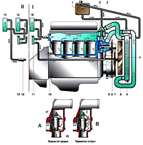
Diagram of the cooling system of the ZMZ-402 and UMZ-4215 engines: I – with one heater; II – with two heaters and an electric pump (for vans with two rows of seats and buses); 1 – expansion tank; 2 – thermostat; 3 – coolant temperature indicator sensor; 4 – radiator; 5 – radiator drain plug (cock); 6 – fan; 7 – fan drive belt; 8 – coolant pump drive belt; 9 – coolant pump; 10 – drain valve of the cylinder block; 12 – electric pump of the heating system; 11, 13 – heater valve; 14 – additional heater radiator; 15, 16 – main heater radiator; 17 – main thermostat valve; 18 – bypass valve.
The car is equipped with a faucet 2 of the heater radiator with an electric drive.
In one body there is a faucet connected through a mechanical gearbox by a microelectric motor activated by handle 1.
The faucet has two positions - fully open or completely closed, until the handle is turned 90° to the right from the original position, the valve is closed, when the handle is further turned to the right until it stops, the valve is open.
In the drain branch of the heater radiator, at its highest point there is a tee 7.
The tee is located in the cab under the instrument panel on the right side.
When the plug 8 of the tee is turned out 2-3 turns, the heating system communicates with the atmosphere, which allows you to completely eliminate air pockets when filling the engine cooling system and heating system with working fluid.
Maintaining the correct engine temperature has a decisive impact on engine wear and efficiency.
The optimal coolant temperature (85-90° C) is maintained using an automatic thermostat and a cover on the radiator lining.
To monitor the coolant temperature, there is a temperature gauge, the sensor of which is screwed into the thermostat pipe located on the cylinder head.
In addition, there is an indicator on the instrument panel that lights up red when the liquid temperature rises above 105° C.
The indicator sensor is located in the rear cover of the cylinder head.
When the indicator lights up, the cause of overheating must be immediately identified and eliminated.
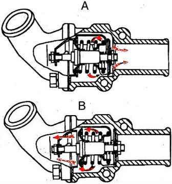
Thermostat with solid filler, two-valve, type TS-107-01 is located in the outlet pipe of the cylinder head and is connected by hoses to the coolant pump and radiator.
The main thermostat valve begins to open at a coolant temperature of 78-82° C. At a temperature of 94° C it is already fully open.
When the main valve is closed, the liquid in the engine cooling system circulates, bypassing the radiator, through the open additional thermostat valve inside the engine cooling jacket.
When the main valve is fully open, the secondary valve is closed and all fluid passes through the cooling radiator.
The body heater is connected in parallel with the radiator, and the thermostat does not disconnect it from the engine.
Therefore, when warming up the engine, you should not open the air intake damper and turn on the heater motor.
The thermostat automatically maintains the required temperature of the coolant in the engine by turning off and on the circulation of fluid through the radiator.
In cold weather, especially at low engine loads, almost all the heat is removed as a result of cold air blowing over the engine, and coolant does not circulate through the radiator.
To maintain optimal engine temperature conditions at subzero ambient temperatures, it is necessary to cover the radiator trim with a cover.
Under no circumstances should you remove the thermostat.
In the cold season, an engine without a thermostat takes a long time to warm up and operates at a low coolant temperature.
As a result, its wear accelerates, fuel consumption increases, and abundant deposition of resinous substances occurs in the engine, and the normal air temperature in the car cabin is not ensured.
In the warm season, in the absence of a thermostat, most of the coolant will circulate in a small circle (through the engine cooling jacket), bypassing the radiator. As a result, this will cause the engine to overheat.
Coolant pump is centrifugal type.
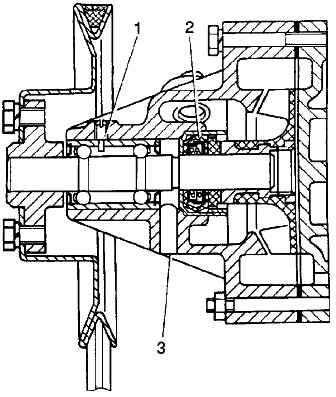
The pump bearing is separated from the coolant by a self-clamping seal of a non-separable design.
Liquid leaked through the oil seal does not enter the bearing, but flows out through inspection hole 3, which must be periodically cleaned.
The pump bearing is prevented from moving by clamp 1, which is screwed in until it stops and is cored.
The bearing is filled with grease during assembly, and no additional grease is required during operation.
The coolant pump pulley is driven into rotation together with the generator pulley by one V-belt from the crankshaft pulley.
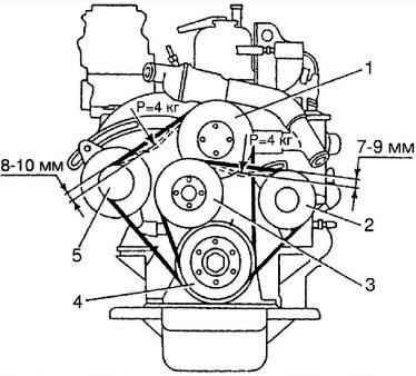
Fan - six-blade, plastic.
Driven by a V-belt from the crankshaft. The fan rotates in two bearings.
The bearings are installed in a special bracket, secured to the timing gear cover with three pins.
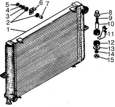
The radiator is tubular-tape, with side plastic tanks.
The tanks are connected to the radiator frame through a rubber sealing gasket by crimping the support plate onto the flange of the plastic tanks.
On the tanks and the top plate of the radiator frame there are brackets for attaching the radiator to the car body.
On the right tank (along the direction of the car) in the lower part there is a drain plug for draining the coolant.
The expansion tank is plastic, connected by a hose to the pipe supplying cooled liquid from the radiator to the engine, and by a tube to the thermostat pipe and the left radiator tank.
The tank has a MIN mark - the lowest permissible level of coolant in the tank.
The expansion tank is closed with a screw plug that maintains increased pressure in the cooling system.
The expansion tank plug, which hermetically closes the cooling system, has two valves: steam, opening at a pressure of 80-110 kPa (0.8-1.1 kgf/cm 2), and air, opening at a vacuum of 1.0-10 kPa (0.01-0.1 kgf/cm 2).
")

")
")
")
")
")
")
")