The microprocessor control system for a gasoline internal combustion engine ZMZ-40524.10 is designed:
- to ensure optimal engine operation in all modes, taking into account fuel efficiency, toxic emissions in exhaust gases, starting and driving characteristics of the vehicle;
- for automated monitoring of the technical condition of the engine and control system elements responsible for compliance with toxicity standards, as well as external diagnostics in accordance with the requirements of EOBD (European On-board Diagnostics).
A feature of the ZMZ-40524 engine control system is:
- the use of a throttle module with an electric motor, which allows you to adjust the position of the throttle valve electronically to obtain the optimal mixture and the required characteristics of torque flow on the car;
- use of a drainless fuel line assembled with injectors with operating pressure in the line (400±8 kPa), to reduce the evaporation of gasoline vapors;
- use of individual ignition coils to reduce the level of interference;
- implementation of the European on-board diagnostic system EOBD, which monitors the technical condition of system components responsible for exceeding the limit values of harmful substances in vehicle exhaust gases.
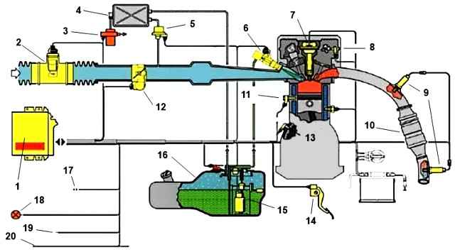
Sensors and control system components located on the engine
Synchronization sensor (engine crankshaft position) DG-6K0 261 210 302 Bosch (40904.3847010) or similar, inductive type, located on the chain cover near the crankshaft pulley.
Generates an electrical signal when the magnetic field of the sensor interacts with a special toothed disk (60-2 teeth) mounted on the crankshaft pulley.
The mutual orientation of the synchronization disk and the sensor is such that the moment the axis of the escape sensor passes the twentieth tooth of the synchronization disk corresponds to the location of the piston of the first and fourth cylinders at top dead center.
The tooth number is counted from the skip in the direction opposite to the rotation of the engine crankshaft.
The sensor is designed to determine by the control unit the angular position and rotation speed of the engine crankshaft.
Phase sensor (camshaft position) PG-3.8 0232103048 Bosch (40904.3847000) or similar, Hall effect, located on the cylinder head.
Generates a signal when the magnetic field of the sensor interacts with a marker (bent plate) mounted on the exhaust camshaft.
The moment the phase sensor begins to generate a signal, if the run of the first tooth of the disk 60-2 coincides with the axis of the synchronization sensor, indicates the beginning of the compression stroke in the first cylinder.
The tooth number is counted from the skip in the direction opposite to the rotation of the engine crankshaft (see crankshaft position sensor).
The phase sensor is designed to determine by the control unit the phase of the working cycle in the engine cylinders.
Electric throttle module with throttle position sensor ETB TS A2C5 330 30 ph. Siemens (40624.1148090).
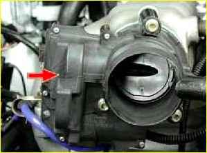
Drive - DC motor with on-board voltage, damper position sensor - magnetoresistive (two-channel).
The throttle module is located on the inlet pipe.
The throttle module is designed to control the filling of engine cylinders with air during start-up, warm-up, idling modes, when turning on/off external power consumers, at various loads - in order to optimize torque.
The sensor is designed to determine the throttle angular position by the control unit.
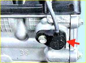
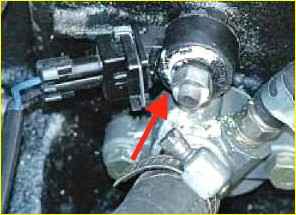
Coolant temperature sensor (engine temperature)
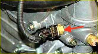
TF-W0 280 130 093 Bosch or similar, (40904.3828000).
The sensor is located on the thermostat housing.
The sensor is designed to measure the engine coolant temperature by the control unit.
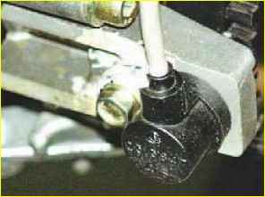
Knock sensor (Fig. 6) KS-4-S0 261 231 176 Bosch (40904.3855000*) or similar, piezoelectric, located on the cylinder block on the intake side, in the area of the 4th cylinder.
The sensor is designed to detect detonation combustion in the engine by the control unit.
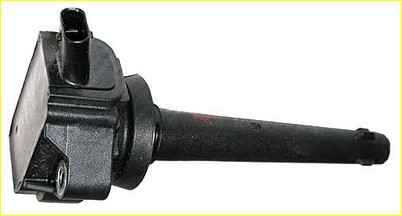
Ignition coils (Fig. 7) ZS-K-1x1 0 221 504 027 Bosch (40904.3705000) or similar, individual, four, transformer type, installed on the valve cover.
Designed to generate high voltage energy to spark plugs.
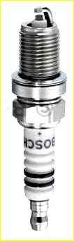
Spark plugs (Fig. 8) DR17YC Bosch or similar, small-sized, with noise suppression resistor, four, screwed into the cylinder head in the center of the combustion chambers.
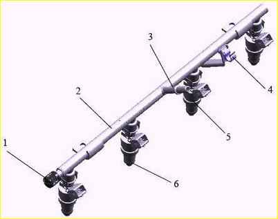
Fuel rail (Fig. 9) (fuel distribution line) with electromagnetic injectors ZMZ6354 (DEKA1D) Siemens assembled (40624.1100010*).
Placement on the inlet pipe. The ramp is drainless, steel, with a fitting for a quick-release coupling.
The fuel rail is designed to supply fuel to the engine cylinders.
Sensors and control units located on the vehicle
Mass air flow sensor (Fig. 10) DMRV 20.3855-10 (HFM62C/19 Siemens), hot-wire, film, located between the air filter and the engine throttle pipe.
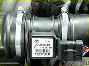
The air flow sensor is designed for the control unit to determine the air flow (cylinder filling) of the engine.
The MAF has a built-in temperature sensor, thermistor type.
The sensor is designed to measure the intake air temperature by the control unit.
Oxygen sensors (lambda probes) OSP+ 25368889 f. Delphi, two, zirconium, with controlled electric heating.
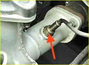
- (1) the main lambda probe, located before the converter, on the exhaust pipe of the vehicle exhaust system. Designed for the control unit to determine the composition of the mixture before the converter (at the engine outlet).
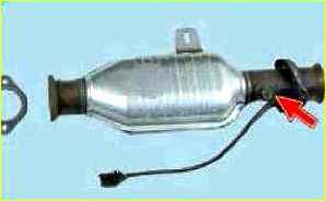
- (2) additional lambda probe, located in the converter body, at its outlet. Designed to determine by the control unit the composition of the mixture after the converter.
The heating circuits of the oxygen sensors are controlled directly from the control unit.
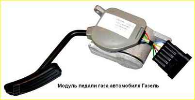
Accelerator pedal module (Fig. 13) 6PV010 033-00 f. Hella, placement in the car.
Designed for the driver to set the engine load.
The pedal mechanism has a built-in pedal position sensor, potentiometric, two-channel.
Designed for the control unit to determine the position of the accelerator pedal.
Rough road sensor (Fig. 14) 2123.1413130-03 or 28.3855000, piezoelectric, located on the car body, in the area of the front suspension shock absorbers.
The sensor measures the acceleration that occurs when the vehicle moves on an uneven road.
The sensor is designed to detect vibrations of the vehicle body transmitted to the transmission by the control unit.
Vehicle speed sensor (Fig. 15) 343.3843 or ADS-6 NK, Hall effect, located on the gearbox speedometer drive.
Designed for measuring vehicle speed by the control unit.
Gasoline vapor adsorber 21103-1164010 with purge valve 21103-1164200, electromagnetic, located in the engine compartment of the car.
Designed to capture fuel vapors from the gas tank and accumulate them in the adsorber.
On a command from the control unit, the valve switches the line connecting the adsorber and the engine intake pipe (supply through a fitting, behind the throttle module). The valve is designed for purging (regeneration) of the adsorber.
Submersible fuel pump module with electric drive, fuel pressure regulator (Fig. 16) (400±8 kPa), coarse filter and fuel level sensor, placed in the car’s gas tank
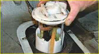
The module is designed to maintain constant fuel pressure in the line.
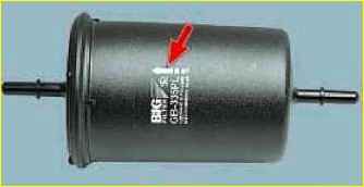
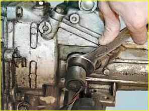
Fuel fine filter (Fig. 17) 315195-1117010 (FTO15-1117010) or 315195-1117010-01 (NF-014-T), placed in the fuel line, between the fuel pump module and fuel rail.
The filter is designed to filter out particles in the fuel.
Clutch engagement sensor 15.3720, switch, switches the on-board power supply voltage +12 V, as a sign that the clutch is engaged, to the control unit, located on the clutch pedal.
Designed to identify by the control unit the moment the gear is turned on/off to determine the engine operating mode (idling, transmission engaged) and throttle control parameters.
Brake sensor 21.3720, two-channel switch, located on the brake pedal.
Switches two signals simultaneously when you press the brake pedal:
- breaks the +12 V on-board voltage circuit to the control unit (a sign of pressing the brake pedal);
- switches the supply of on-board voltage +12 V to the "stop lamp" and to the control unit (indication that the "stop lamp" is turned on).
The sensor is designed to provide the control unit with the function of monitoring the safety of throttle control.
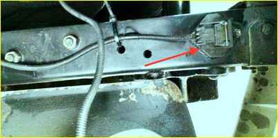
Diagnostic connector - 16-pin OBD-II J1962 connector, located inside the car on the accelerator pedal bracket.
The connector is designed to ensure information exchange between the control unit and diagnostic equipment via a single-wire K-line communication line in accordance with ISO 9141-2.
The control unit memory stores vehicle operating parameters and fault information in the form of fault codes, available for reading by diagnostic equipment through the diagnostic connector.
Relay electromagnetic, placement in the engine compartment of the car, 90.3747000-10 or another type.
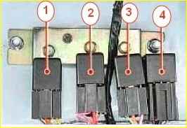
Designed for switching the voltage of the vehicle’s on-board network upon command from the control unit:
- (Main) - on actuators, control system sensors and control unit;
- (gasoline pump) - to the electric drive of a submersible gasoline pump;
- (fan clutch) - on the electromagnetic clutch of the cooling system fan drive.
Diagnostic indicator - a yellow (orange) lamp with a motor symbol, located on the vehicle’s instrument panel.
The indicator is designed to indicate disturbances in the functioning of the control system and the performance of on-board diagnostic functions EOBD.
The malfunction indicator operates in three modes:
- off (no faults);
- continuous light (presence of malfunctions) - serious violations affecting toxic emissions and control functions that require elimination;
- flashing indication (0.5 sec - on, 0.5 sec - off) - when registering an unacceptable level of misfires followed by shutting off the fuel supply to the engine cylinder (continuous light), indicating an immediate stop of the vehicle to prevent damage to the converter and traffic safety violations.
When the ignition is turned on, the indicator should turn on, and if the on-board diagnostics does not detect any faults, it should go out after 3-5 seconds.
The absence of a lamp indication before starting the engine indicates a violation in the indicator control circuit, which is unacceptable during operation.
Continued lighting of the indicator after turning on the ignition switch indicates the presence of malfunctions.
Starting the engine and driving the vehicle when the malfunction lamp is illuminated, in order to prevent damage to the converter or disruption of control functions, without first diagnosing the system is undesirable.
Control unit 371.3763 Mikas 11ET, (Fig. 19) microprocessor, located in the engine compartment of the car.
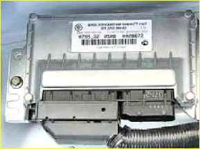
The design of the control unit may vary depending on the vehicle configuration.
Control system wiring harness, 3302-3761581 or another name, depending on the vehicle configuration.
The control system prevents emergency operating modes:
- exceeding the maximum crankshaft speed (except for forced engine cranking) - by cutting off the fuel supply to the cylinders;
- detonation combustion;
- maintains the coolant temperature within the operating range by controlling the operation of the electromagnetic fan clutch;
- detects misfires and calculates the temperature of the exhaust gases at the engine outlet, followed by shutting off the fuel supply to the faulty cylinder when the misfire limit value is reached;
- calculates the temperature of the converter, and if the temperature threshold is exceeded, enriches the air-fuel mixture (during normal operation of the engine cylinders);
- registers and stores information about emergency operation conditions.
The control system allows the vehicle to move when the sensors are faulty, without guaranteeing that the engine and vehicle specifications will be maintained:
- if the mass air flow sensor fails;
- if the intake air temperature sensor fails;
- if the coolant temperature sensor fails;
- if one of the throttle valve position sensors fails;
- in case of minor malfunctions of the electric throttle drive;
- if one of the electric accelerator pedal position sensors fails;
- if one oxygen sensor (or its heater circuit) fails - to the converter;
- if the oxygen sensor (or its heater circuit) fails - after the converter;
- if the knock sensor fails;
- if the camshaft position sensor fails (transition to pairwise parallel fuel injection and ignition);
- if there is a malfunction of the fuel vapor recovery system and the canister purge valve;
- if the vehicle speed sensor fails;
- if one of the brake limit switches is faulty;
- if the brake pedal switch is faulty;
- if the clutch limit switch is faulty;
- if the air conditioning compressor clutch relay fails;
- if the rough road sensor fails.
During operation of the control system, servicing of its individual components, including the control unit, is not provided.
Restoring the normal functioning of the control system is carried out by replacing its elements.
To diagnose the ZMZ-40524 engine management system, the ASKAN-10 diagnostic tester with the PM Mikas 11 Euro 3 (DM11 E3) software module and an OBDII connecting cable is used.
")

")
")
")
")
")
")
")