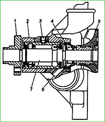
Centrifugal type water pump. Located and secured on the chain cover
The roller bearing 7 is separated from the coolant by a self-tightening oil seal 4 of a non-separable design, inside of which there is a cuff and a sealing washer
The liquid leaking through the oil seal does not enter the bearing, but flows out through inspection hole 6, which must be periodically cleaned.
The bearing is prevented from moving by clamp 3, which is screwed in until it stops and is cored.
The bearing is filled with lubricant during assembly; no additional lubricant is required during operation.
Hub 1 and impeller 5 are pressed onto the bearing shaft.
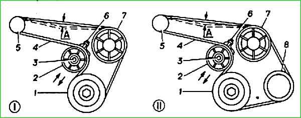
The water pump and generator are driven by a poly-V belt. During operation, it is necessary to periodically check its tension.
The deflection arrow “A” (Fig. ) between generator pulley 5 and water pump pulley 7 when pressed with a force of 8 daN (8 kgf) should be 15 mm.
Belt tension is adjusted by tension roller 2, equipped with a fastening bolt 3 and a movement bolt 6.
To adjust the belt tension you need to:
- - loosen bolt 3 securing the tension roller;
- - use the movement bolt 6 to install roller 2 in a position that provides the required belt tension;
- - tighten the tension roller bolt;
- - check the belt deflection.
The fan* is plastic, six-blade, mounted on the hub of the water pump drive pulley through a threaded bushing with a left-hand thread M24x1.
On buses with 6 passenger seats, instead of a belt-driven fan, an electric fan with automatic activation is installed.
Removing the water pump
Drain the engine cooling system.
Remove the radiator.
Remove the generator drive belt.
For engine 4062

Unscrew the three bolts 1, holding the pump shaft from turning with a screwdriver 2, and remove the reflector 3 and pulley 4 of the water pump.

Unscrew fitting 3 and disconnect tube 4 from the pump.
Unscrew the pump mounting bolt 1, loosen the clamps 2.

Disconnect radiator outlet hose 1 from the pump by loosening clamp 2.

Unscrew the fastening bolts 1 and remove the water pump 2 and the water pump gasket.
For engine ZMZ-402

Unscrew four bolts 1 and remove fan 2 and fan pulley 3.

Disconnect hose 2 for draining fluid from the heater from the water pump by loosening clamp 1.
Disconnect hose 3 from the pump by loosening clamp 4.

Unscrew the fastening nuts 1 and remove the pump 2 with the pump gasket.
Disassembling the water pump
Pumps installed on engines mod. 4062 and 402, similar in design.
Here is shown the disassembly of the engine pump mod. 4062.
The engine pump mod. 402, you must first unscrew the two bolts and remove the pump cover with the gasket.
The following procedure for disassembling both pumps is the same.

Remove pump impeller 1 using a puller.
The impeller is cast from plastic, but has a metal hub with a thread for a puller.

Use a puller to compress the hub 1 of the pump pulley.
Unscrew the bearing retainer 2 and press the bearing with the pump shaft towards the pulley.

Press out the oil seal of pump 1.
Rinse and remove deposits from the pump parts.
Inspection of water pump parts
The bearing on the pump shaft must rotate freely, without jamming, otherwise replace the bearing and shaft assembly.
If a large amount of play is felt in the bearing, traces of lubricant leakage from under the protective rings are noticeable, or balls roll when the bearing rotates, it must be replaced as an assembly with the roller.
Inspect the impeller. If there are cracks, chips, etc., replace it.
Inspect the oil seal. If there are tears, cracks, the rubber has lost its elasticity, the preload spring is broken, replace the oil seal.
Assembling the water pump
Pressing on the pulley hub and water pump impeller

- A = (117.5±0.2) mm (engines mod. 402 and 4021);
- B = 0 / 0.2 mm (motors mod. 402 and 4021);
- C = 0.9 / 1.3 mm (engine mod. 4062)
The pump is assembled in the reverse order of disassembly.
When assembling the pump, inspect the gaskets; if there are tears on them or the gaskets are too compressed, they must be replaced.
When pressing the impeller and hub, the emphasis should be on the pump shaft.
When assembling the pump, maintain the dimensions indicated in the figure.
After screwing the bearing retainer, you need to open the edges of the hole so that part of the metal fits into the slot of the retainer to prevent self-unscrewing.
Installation is carried out in the reverse order of removal.
")

")
")
")
")
")
")
")