Reducing pressure in the power system
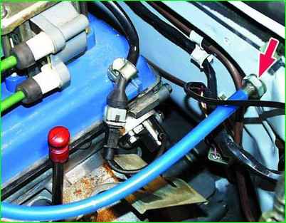
Remove the fuel pump fuse from the fuse box
Start the engine and let it run until the fuel is completely exhausted from the fuel line. After this, the engine will stall.
Insert the fuse.
Replace damaged chain guides.
After this, you can disconnect the fuel lines.
Replacing the mass air flow sensor
Disconnect the wire from the negative terminal of the battery.
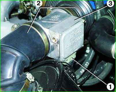
Disconnect block 1 from mass air flow sensor 3.
Loosen the clamps, disconnect the air supply hoses 2 and remove the sensor 3.
Install the new sensor in reverse order.
Checking the mass air flow sensor
Remove the mass air flow sensor.
Connect a voltmeter to contacts “2” and “3” of the sensor connector. Apply a direct current of 12 V to pins “1” and “5” to pin 5, and <—> by 1. In this case, the voltmeter should show a voltage of 1.3-1.4 V.
Then briefly close contacts “4” and “5” with each other. The voltmeter should show a voltage of about 8 V and the platinum thread should become red hot.
If at least one of these conditions is not met, replace the sensor.
Adjusting the carbon monoxide (CO) content in exhaust gases
Adjustment is carried out on a warm engine (coolant temperature 80–90°C) with a working ignition system and nominal gaps between the spark plug electrodes.
The content of CO and CH in the exhaust gases must be within the limits:
- 0.7–0.9% CO and 1200 million –1 CH at crankshaft speed (800±50) min –1 ;
- no more than 0.5% CO and 600 million –1 CH at crankshaft speed (3150±50) million –1 .
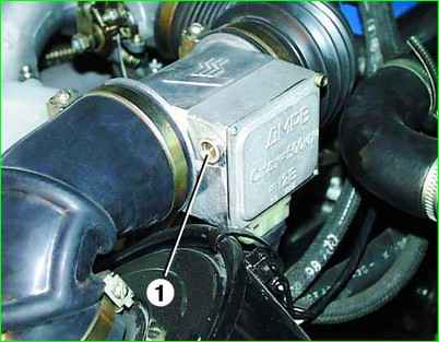
If the CO content is above the specified limits, adjust the CO content with screw 1 on the mass air flow sensor.
When turning the screw clockwise, the CO content increases, and counterclockwise, it decreases. In this case, the content of CH will also be adjusted.
If it is not possible to adjust the CO and CH content within the specified limits, you need to check the serviceability of the elements of the integrated microprocessor engine control system.
Replacing the accelerator cable
Disconnect the wire from the “Negative” terminal of the battery.
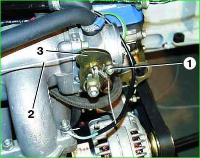
Unscrew nut 1 and remove accelerator cable 2 from sector 3 of the air throttle valve drive.
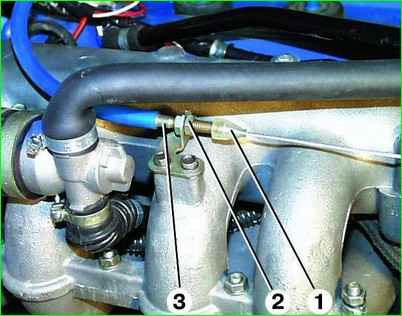
Move the oil seal 1 from the cable tip, completely unscrew the nut 2 from the cable tip, pull out the cable shell tip 3 from the bracket and lift the cable up from the bracket through the slot.
Remove tip 3 from the cable by removing it from the outer 4 and inner sheaths of the cable.
Remove the outer 1 and inner sheaths of the cable from the tip 2 on the front panel.
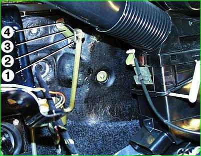
Remove cotter pin 1 from pin and remove pin 2. Move oil seal 4 and remove bracket 3
Pull the cable through the end on the front panel into the passenger compartment.
Install the new accelerator cable in reverse order and adjust it.
Adjusting the accelerator cable
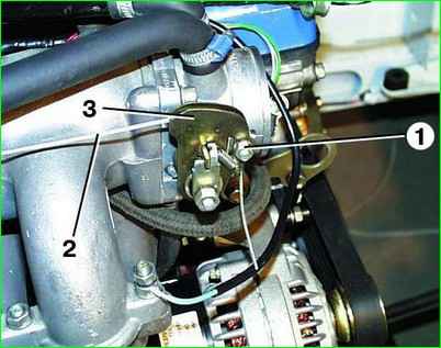
Loosen the tightening of nut 1 securing cable 2 on sector 3.
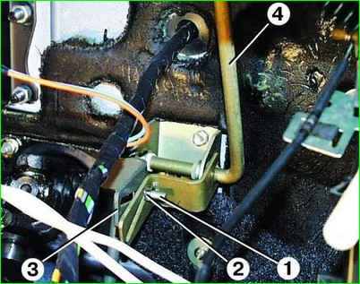
Loosen the tightening of nut 2 of adjusting bolt 1 between the upper 4 and lower 3 levers of the accelerator pedal.
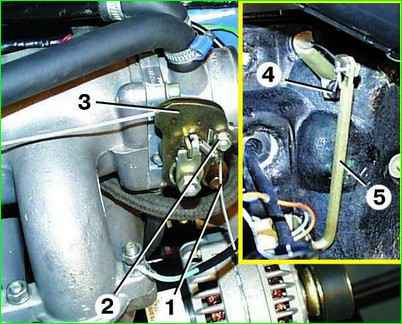
From sector 3 of the throttle valve, pull out cable 1 until it stops.
In this case, the upper lever 5 of the accelerator pedal should rest against the buffer 4 on the bracket. Tighten nut 2 securing the cable to the sector.
In this case, the throttle valve must be completely closed.

Pull the upper lever of the 4th pedal towards you until it stops.
Holding the upper pedal lever 4 in this position, turn the lower pedal lever 3 until it stops on the mat and tighten the nut 2 of the adjusting bolt 1
If adjusted correctly, when the pedal is fully released, it is completely closed, and the upper lever of the pedal rests against the buffer on the bracket.
When the pedal is fully depressed, the throttle valve should be fully open and the lower pedal arm should rest against the mat.
In this case, the throttle valve must be completely open.
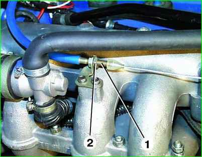
You can correct the position of the cable by moving the tip 1 of the shell in the bracket, loosening the tightening of the nut 2.
After adjusting nut 2, tighten
Throttle assembly
Removal
Disconnect the wire from the negative terminal of the battery.
Disconnect the accelerator cable from the throttle sector
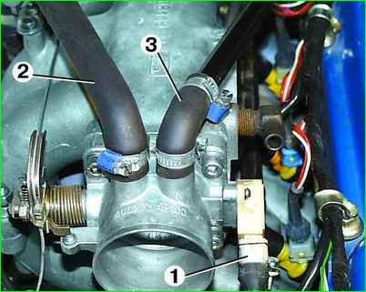
Disconnect block 1 with wires from the throttle position sensor.
Loosen the clamps and disconnect the hoses of the idle air control 2 and crankcase ventilation 3.
Loosen the clamps and disconnect hoses 1 of the throttle heating, having previously marked them.
Immediately plug the hoses with plugs to avoid loss of coolant.
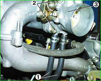
Unscrew the four fastening bolts 2 and remove the throttle 3 with the gasket.
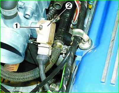
If it is necessary to remove the throttle position sensor 2, unscrew the two screws 1 securing it
Replacing the idle speed control
Disconnect the wire from the negative terminal of the battery.
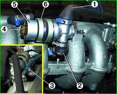
Loosen the clamps and disconnect hoses 1 and 2 from regulator 5.
Disconnect the block with wires from connector 4 of the regulator.
Unscrew the two mounting bolts 3 and remove the regulator.
Remove regulator 5 from clamp 6.
Install the new idle air control in reverse order
Checking the idle air control
Remove the idle air control.
Apply a direct current of 12 V to the middle contact of the regulator connector and alternately to the side contacts
In this case, the damper should rotate, opening or closing the opening of the inlet channel. If this does not happen, then the regulator is faulty and needs to be replaced.
Replacing injectors
Reduce the pressure in the power system if the engine has just been stopped.
Disconnect the wire from the negative terminal of the battery.
Remove the receiver.
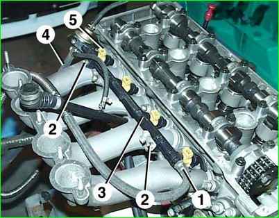
Loosen the clamps and disconnect the fuel supply hose 1 from the engine fuel line 3.
Disconnect fuel drain hose 4 from the pressure reducing valve.
Disconnect the connectors with wires from connectors 5 of the four injectors.
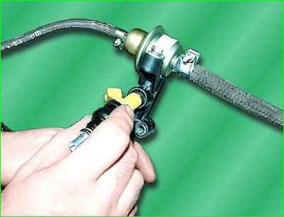
Remove the injector from the engine fuel line. The injector is fixed in the hole in the fuel line only with the help of an O-ring.
Unscrew the two fastening bolts 2 and carefully remove the fuel line 3 of the engine, removing the injectors from the holes in the intake pipe.
The injectors are fixed in the holes of the intake pipe only with the help of O-rings.
Install the new injector in reverse order.
Checking the injectors
To check the tightness of the injector valve, you need to lower the sprayer of 1 injector into a container with gasoline or kerosene and apply compressed air at a pressure of 0.3 MPa (0.03 kgf/cm).
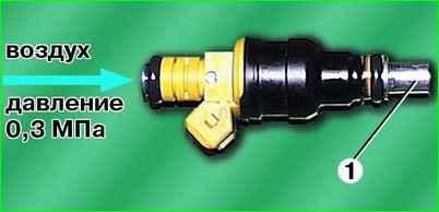
If air bubbles come out of the injector nozzle, the injector valve is leaking and the injector must be replaced.
to check the serviceability of the injector electromagnet winding, apply a direct current of 12 V to the injector connector.
In this case, a characteristic click should be clearly audible, indicating the opening of the nozzle valve.
If this does not happen, then the injector is faulty and must be replaced. This check can be carried out without removing the injector from the vehicle.
The resistance of the injector solenoid winding can be checked with an ohmmeter by connecting it to the contacts of the injector connector.
The resistance should be in the range of 15.5-16 Ohms. If the resistance value does not fall within the specified limits, replace the injector.
Replacing the pressure relief valve
Reduce pressure in the power system if the engine has just been stopped.
Disconnect the wire from the negative terminal of the battery.
Remove the engine fuel line.
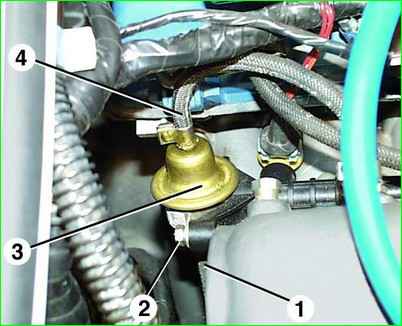
Disconnect fuel drain hose 1 and vacuum hose 4 from pressure reducing valve 3.
Unscrew the two fastening bolts 2 and remove the pressure reducing valve 3 from the engine fuel line.
Install the new valve in reverse order.
Replacing and checking the synchronization sensor
Disconnect the wire from the negative terminal of the battery.
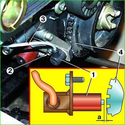
Disconnect the connector for wire 3 of the sensor, located behind the engine intake pipe.
Unscrew bolt 2 and remove sensor 1.
Check the resistance of the sensor coil with an ohmmeter; it should be in the range of 850–900 Ohms.
If the resistance value does not fall within the specified limits, replace the sensor.
Install the sensor in reverse order. For normal operation of the sensor, the gap “a” between sensor 1 and synchronization disk 4 must be within 1.0–1.5 mm.


