Setting the ignition timing of a GAZ-2705 with a 402 engine
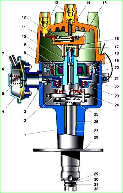
The ZMZ-402 engine is equipped with an ignition distributor sensor (1908.3706) - non-contact, with a control pulse sensor (generator) and built-in vacuum and centrifugal ignition timing regulators
The distribution sensor performs two functions: it sets the moment of sparking and distributes high voltage pulses among the cylinders in accordance with their operating order.
For this purpose, use a slider mounted on the shaft of the sensor-distributor.
The slider has a noise suppression resistor*.
The switch (1313734) opens the power circuit of the primary winding of the ignition coil, converting the sensor control pulses into current pulses in the ignition coil.
Adjusting the ignition timing of the ZMZ-402 and UMZ-4215 engines
Install the crankshaft in a position corresponding to the ignition timing angle of 5°.

To do this, on the ZMZ-402 engine we combine the middle mark on its pulley with the tide on the block cover (the end of the compression stroke of the first cylinder).

For the UMZ-4215 engine, place the first mark on the pulley against the pin on the timing gear cover.

If the distributor sensor is not removed from the engine, then the compression stroke of the first cylinder is determined by removing the distributor cap; the slider should be against the internal contact of the cover, connected by a wire to the spark plug of the first cylinder.
Otherwise, turn out the spark plug of the first cylinder. Closing the hole with a paper stopper, rotate the crankshaft.
The air that pushes out the plug will indicate the beginning of the compression stroke.

Use a 10mm wrench to loosen the octane corrector screw

Set its scale to zero division (middle of the scale).

Using a 10mm wrench, loosen the screw securing the octane corrector plate

By rotating the housing of the sensor-distributor, we align the “marks” (the red mark on the rotor and the arrow on the stator). Holding the sensor in this position, tighten the screw.
Make sure that the slider is located against the contact of the cover of the first cylinder and check that the high-voltage wires are connected correctly steel cylinders - counting counterclockwise from the first cylinder in the order 1–2–4–3.
After you have done everything, check that the ignition timing is set correctly while the car is moving.
We start the engine, warm it up, and when we have already switched to fourth gear at a speed of 50 - 60 km/h, sharply press the gas.
If detonation (the sound is similar to the knocking of valves) appears briefly - for 1-3 s - the ignition timing is chosen correctly.
Prolonged detonation indicates an excessive ignition timing, reduce it with an octane corrector by one division.
The absence of detonation requires an increase in the ignition timing, after which the test must be repeated.
A more accurate setting of the ignition timing can be checked using a strobe light in accordance with the instructions included with the strobe light.
Technical characteristics of the ignition system
- Cylinder operating order 1–2–4–3
- The direction of rotation of the distributor rotor is counterclockwise
- Ignition timing max, degrees:
- centrifugal regulator 15–18
- vacuum regulator 8–10
- Spark plug gap 0.8 mm
- Slider resistor resistance* 5–8 kOhm
- Candle tip resistance 4–7 kOhm
- Resistance of the central contact of the cover* 8–13 kOhm
- Stator winding resistance 0.4–0.45 kOhm
* On some of the sensors, instead of a resistor, a cover with a central carbon contact is installed.
")

")
")
")
")
")
")
")