The cylinder block and head do not require maintenance, except for cleaning dust and dirt and tightening threaded connections
Over time, the cylinder head gasket is dented, so it is possible that the head nuts may loosen, the gasket may burn out, and gases may leak out, so during operation, the cylinder head must be tightened every 20,000 km of the vehicle.
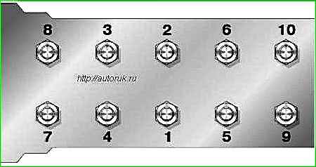
The nuts of the cylinder head mounting studs are tightened from the middle of the head to the ends (front and rear).
Tightening and checking the tightening torques should be done on a cold engine.
If this operation is performed on a hot engine, then after it cools down, the tightening of the nuts will be incomplete due to the large difference in the coefficients of linear expansion of the material of the head, block and studs.
For a uniform and tight fit of the head to the block, tightening should be done in two steps: first - with low force and finally - with a specified torque of 83-90 Nm (83-9.0 kgcm).

It should be borne in mind that tightening the nuts causes a change in the clearances in the gas distribution mechanism. Therefore, after each such operation it is necessary to check the size of the gaps between the rocker arms and valve stems.
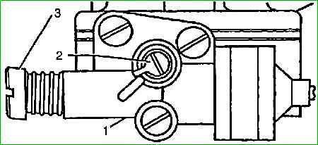
If necessary, thermal clearances must be adjusted. To ensure a tight and uniform fit of the rocker cover gasket to the cylinder head, the rocker cover mounting bolts should be tightened in the sequence shown in the figure.
During the operation of an engine, especially a worn one whose rings leak a lot of oil, a layer of soot is deposited on the walls of the combustion chamber and the piston heads.
Soot impairs heat transfer through the walls into the coolant, resulting in local overheating, detonation and glow ignition phenomena, engine power decreases and fuel consumption increases.
If such signs appear, remove the head and clean the combustion chamber and piston bottom from carbon deposits.
Before cleaning, the carbon deposits should be moistened with kerosene. This prevents the spraying of carbon deposits and prevents toxic dust from entering the respiratory tract.
Soot also forms during long-term operation at low loads of a serviceable, unworn engine.
In this case, the carbon burns out during prolonged movement at high speed.
When removing the cylinder head, it is recommended to grind the valves.
During operation, every 20,000 km of the vehicle, it is necessary to check and adjust the gap between the valves and rocker arms. This should be done on a cold engine (+20° C) with the cylinder head fastening nuts and the rocker arm mount nuts tightened.
Thermal gap between the rocker arms and valves should be within 035-045 mm.
With increased clearances, valve knocking occurs, and with reduced clearances, the valve may not fit tightly to the seat and the valve may burn out, so the above clearance values should not be reduced even if there is some knocking, which, although unpleasant to the ear, does not cause disruption to normal operation engine.
Check and adjust thermal clearances in the following sequence:
- - set the piston of the 1st cylinder to TDC of the compression stroke. To do this, turning the crankshaft with a special wrench, align the third mark on the damper part of the crankshaft pulley with the indicator rib on the timing gear cover.
During the compression stroke, both rocker arms of the 1st cylinder should swing freely on their axles, i.e. both valves are closed.
Check the gap between the rocker arm and the valve with a feeler gauge.
If the gap is incorrect, unscrew the adjusting screw nut with a wrench and turn the adjusting screw with a screwdriver to set the gap according to the feeler gauge.
Support the adjusting screw with a screwdriver, lock it with a nut and check the correct clearance;
- - turn the crankshaft half a turn, adjust the clearances for the 2nd cylinder;
- - turn the crankshaft another half turn, adjust the clearances for the 4th cylinder;
- - turn the crankshaft another half turn, adjust the clearances for the 3rd cylinder.
When operating the vehicle, you should check the oil level in the crankcase and the tightness of the lubrication system daily.
Every 10,000 km of the vehicle, the oil in the lubrication system and the filter should be changed oil filter element, flush the lubrication system in a timely manner and eliminate any leaks in the connections of parts.
The oil level is checked with the engine not running using the marks on the indicator rod.
It is recommended to maintain the oil level near the “P” mark.
Increasing the level above the “P” mark is undesirable, since the crank heads of the connecting rods will be immersed in oil and splash it, causing the formation of excessive oil mist in the crankcase.
This causes splashing of the spark plugs, intense formation of carbon deposits on the piston heads and walls of the combustion chamber, coking of the rings, engine smoking and increased oil consumption.
Lowering the oil level below the min mark is dangerous, since this stops the oil supply to the system and the bearings may melt.
The oil level should be checked a few minutes after filling or stopping the engine.
After changing the oil, you need to start the engine and let it run for a few minutes.
After some time, check the oil level as indicated above.
You only need to drain the oil for replacement when the engine is hot. In this case, the oil has a lower viscosity and drains well.
When changing the oil, you should also drain the sediment from the oil filter, clean the inner surface of the housing and the rod, and change the filter element.
The filter element must be soaked in clean engine oil before installation. To ensure a tight fit of the filter cover, it is recommended to place it together with the gasket in the same position as it occupied before removal.
Do not over-tighten the cover bolt, as this may cause the cover to become deformed.
The tightness of the cover is checked after starting the engine.
To prevent unfiltered oil from entering the engine, the rubber sealing rings of the filter element must be elastic and not deformed.
When switching engine operation to another brand of oil, it is necessary to flush the lubrication system with fresh oil of the brand that will be used to lubricate the engine.
To do this, you need to drain the old oil from the crankcase of a warm engine, fill in flushing oil 2-4 mm above the min mark on the oil level indicator, start the engine and run for 15 minutes.
In idling mode at low speed, turn off the engine, drain the oil from the crankcase, replace the filter element and fill with fresh oil.
During operation, top up only the brand of oil that is poured into the engine.
To service the crankcase ventilation system you must:
- - remove the air filter, crankcase ventilation hoses;
- - remove the rocker cover and carburetor;
- - rinse with kerosene and blow air through the rocker cover and hoses;
- - clean the calibrated hole 50 in the housing of the mixing chambers with copper wire 1.5 mm in diameter;
- - ensure the tightness of all connections during assembly.
During operation, operation should not be allowed with the oil filler neck open: this leads to the entry of unpurified air into the engine and causes increased wear of engine parts.
To check the correct assembly and normal operation of the crankcase ventilation system, it is necessary to clamp the hose supplying crankcase gases to the carburetor with the engine running at minimum idle speed.
If the engine speed drops suddenly or the engine stalls, the system is operating normally.
Cooling system care - consists of daily checking the coolant level in the expansion tank.
The fluid level on a cold engine should not be below the MIN mark.
The MIN mark is located on the wall of the expansion tank.
If necessary, add coolant to the expansion tank. In cases of frequent topping up, check the tightness of the cooling system.
When servicing the cooling system, you should keep in mind that Tosol-A 40M, Lena, Thermosol coolants are poisonous and flammable, since they contain ethylene glycol.
By analogy with the latter, liquids have a poisonous and narcotic effect and the ability to penetrate the body through the skin.
If coolant enters the body through the mouth, it causes chronic poisoning with damage to vital human organs (affects blood vessels, kidneys, nervous system).
Therefore, the following precautions must be observed when using coolant:
- - do not suck liquid into your mouth when transfusing it;
- - do not smoke or eat while working with coolant;
- - in cases where splashing of coolant is possible during operation, use safety glasses;
- - exposed areas of skin that have come into contact with coolant must be washed with soap and water.
Every 10,000 km it is necessary to adjust b tension the drive belts of auxiliary units, and also check the tightness of all connections of the cooling system.
If drops or slight moisture are detected, tighten the connection clamps.
In case of significant fluid leaks, water may be used to restore the level in exceptional cases.
However, this will inevitably reduce the density of the mixture and increase its freezing point. Therefore, as soon as possible, you should replace the mixture with new coolant.
When adding water to the cooling system, the level in the expansion tank should be 7-10 cm above the MIN mark.
Before starting winter operation, you should check the density of the liquid in the cooling system, which should be in the range of 1078-1085 g/cm 3 at 20° C.
Every three years, it is necessary to flush the cooling system and fill in new coolant, and it is also recommended to check the operation of the thermostat and the valve block of the expansion tank plug.
Replace the coolant in the following order:
- - place the car on a horizontal platform;
- - make sure that the heater tap is open, to do this, turn on the ignition, turn knob 4 of the air temperature regulator, turn off the ignition;
- - remove the expansion tank cap;
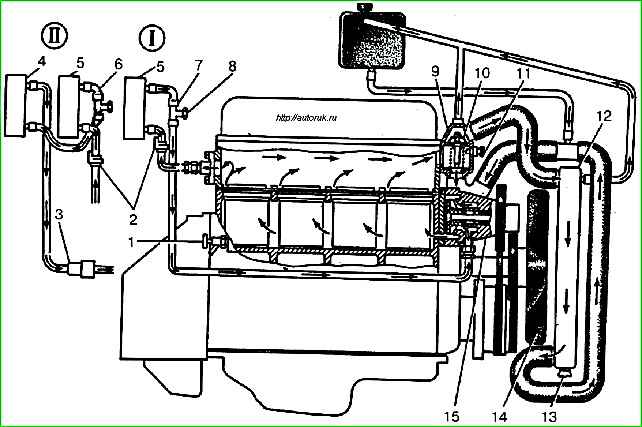
- - drain the coolant from the engine and radiator through tap 1 and plug 13;
- - disconnect the heating system drain hose from the fitting on the engine (on the right side) and the supply hose from the lower heater radiator tube;
- - on GAZ-2705 “Combi” cars and buses, remove the protective cover of the heater hoses on the floor in the cab and disconnect the hoses from the radiator 4 of the auxiliary heater, having previously installed a fluid container under the lower radiator tube;
- - after draining the liquid from the heating system, install the removed hoses in their places.
Rinse the cooling system, for what:
- - tighten valve 1 and radiator plug 13;
- - fill the engine cooling system with clean water through the filler neck of the expansion tank to the normal level and tighten the tank cap;
- - start the engine, warm it up at medium speed to 80-90° C and run for 3-5 minutes;
- - stop the engine and drain the water as indicated above.
Fill the cooling system, for what:
- - tighten the tap on the engine block and the radiator cap. Tee plug 8 (see) should be turned out 2-3 turns;
- - slowly pour liquid into the expansion tank. If the fluid does not leave the tank, then vigorously press the radiator outlet hose 1-2 times to remove accumulated air;
- - if liquid appears from under the tee plug, tighten the plug.
After refueling, you need to start the engine and, idling, warm it up until the main thermostat valve opens.
In this case, on GAZ-2705 “Combi” cars and on buses, you must turn on the electric pump.
Run the engine for 3-5 minutes. (cycles) at different crankshaft speeds: 3000 min -1 - 0.5 min; 1500 min -1 - 0.5 min; minimum idle speed - 0.5 min.
Check the cooling system for leaks.
After the engine has cooled, check the fluid level in the expansion tank and, if necessary, top up to normal.
Checking the operation of the thermostat consists of checking the temperature at which the main valve begins to open, the value and time of its full opening.
To do this, the thermostat is removed from the engine and placed in a tank with coolant with a volume of at least 3 liters and mounted on a bracket so that the entire thermal power element is washed by streams of mixed liquid.
The intensity of liquid heating after 55° C should be no higher than 1° C per minute.
The temperature at which the valve stroke is 0.1 mm is taken as the temperature at which the main valve begins to open. This temperature should be 80° C.
At a temperature 15° C higher than the temperature when the main valve begins to open, the valve's full opening value must be at least 8.5 mm.
The time for complete opening of the main valve is determined from the moment the thermal power element is immersed in liquid at a temperature of about 100° C. This time should be no more than 80 s.
During operation, the following deviations of the thermostat parameters relative to the nominal values are allowed:
- the temperature at which the main valve begins to open is 3° C;
- loss of valve stroke - by 20%.
The simplest check of the thermostat's serviceability can be done by touch directly on the car.
After starting a cold engine with a working thermostat, the hose connecting the thermostat pipe to the right (in the direction of the car) radiator tank should heat up when the coolant temperature reaches 80-90° C.
In this case, the arrow of the coolant temperature indicator should be set to the green zone of the instrument scale.
It is necessary to maintain the correct tension on accessory drive belts.
The deflection of the fan drive belt should be within 7-9 mm, the deflection of the coolant pump and generator drive belt should be within 8-10 mm with a load on each of them of 40 N (4 kgf).
Check with a dynamometer 7870-8679 as follows:
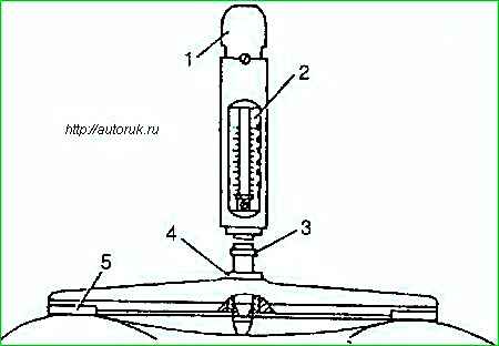
- - install the dynamometer with strap 5 on the pulleys of the fan and tension roller, coolant pump and generator;
- - press handle 1 with your hand until collar 3 touches the rod with bushing 4 and determine the belt tension force on scale 2;
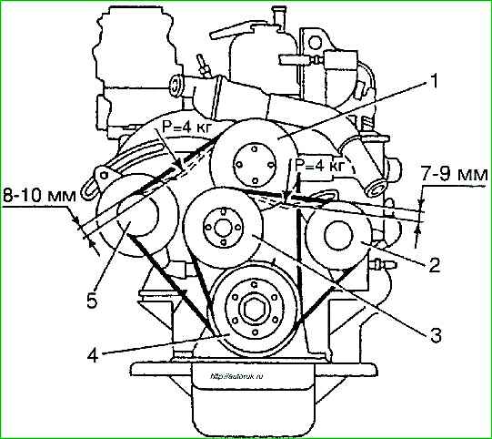
- - adjust, if necessary, the tension of the fan drive belt by changing the position of the tension roller 2, the generator drive belt and coolant pump by changing the position of the generator.
If the belt tension is weak, they slip, which leads to insufficient operation of the fan, coolant pump and generator, as well as to strong heating and delamination of the belts.
Excessive belt tension causes rapid wear of the fan bearing, coolant pump, generator and tension pulley, as well as stretching and destruction of the belts themselves.
Caring for the power supply system. A prerequisite for reliable operation of the power system is the cleanliness of its devices and components.
It is necessary to fill only clean gasoline into the tank, and also periodically drain sediment and water from the tank.
You should carefully check the tightness of connections of fuel lines and other system components in good lighting, at a crankshaft speed corresponding to idle speed.
Leaking fuel creates a fire hazard. Leaks in connections are eliminated by tightening nuts, fittings and clamps.
Maintaining the throttle and air damper drive consists of replacing parts that have failed.
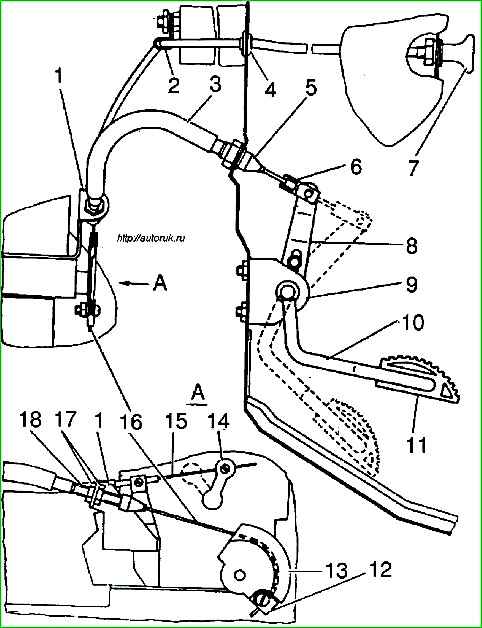
Installation of the throttle valve drive (see) must be done as follows:
- - install tips with seals 5 and 18 in the front panel of the cabin and bracket 7 of the carburetor;
- - thread the cable through the holes of tips 5 and 18 from the cabin side;
- - insert the ends of the inner tube of the shell 3 into the sockets of tips 5 and 18, and put the ends of the outer tube onto the ends of the tips;
- - place the end of the cable with the tip into the socket of the coupling 6 and secure it with a pin with a cotter pin on the pedal lever with the slot up;
- - keeping pedal 11 pressed to the floor mat, and sector 13 in position fully open throttle valves, secure cable 16 to sector 13 using bracket 12;
- - if necessary, adjust the cable tension as accurately as possible by moving the tip 18 in bracket 1 and using nuts 17 (to ensure full opening and closing of the throttle valves);
- - having completed the adjustment, set sector 13 to the position of fully closed throttle valves (pedal in the upper position) and secure the lever limiter 8 in the position of contact with bracket 9.
When installing a flexible rod, do not allow sharp bends in the cable, since if there is a bend in the cable, it may become stuck in the sheath, as well as premature breakage of the cable and wear of the plastic tubes.
Caring for the air filter involves periodically replacing the filter element.
To do this, you need to unfasten the five latches and remove the filter cover.
When assembling the filter, you need to pay attention to the correct location of the sealing gaskets between the filter housing and the filter element, the filter cover, as well as the connection between the housing and the carburetor.
When repairing a filter, parts that have failed are replaced.
Maintenance of the fuel filter-sump consists of periodically draining the sediment (every 20,000 km) through the drain plug, washing the filter housing and its filter element seasonally, once a year.
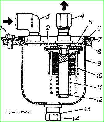
To remove the filter element, you need to unscrew the two bolts securing the sump tank bracket 8 to the frame, unscrew the bolts 1, remove the housing with bracket 8, remove the washer 12 and spring 11.
Rinse the filter element and filter housing with clean unleaded gasoline.
When assembling the sediment filter, you must ensure that gaskets 2 and 6 are installed correctly.
Maintenance of the fine fuel filter consists of periodically cleaning the sedimentation tank from dirt and sediment every 20,000 km, washing the mesh filter element or replacing the paper filter element (for engines manufactured before 2001), replacing the filter assembly (for engines released since 2001).
Maintaining the fuel pump involves periodically removing dirt from the head and washing the strainer.
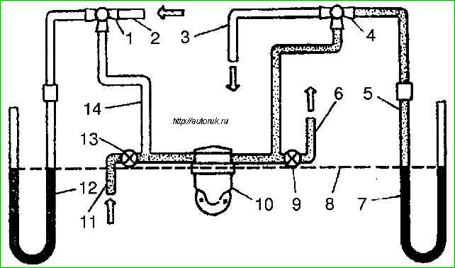
There are two ways to check the pressure developed by the pump.
First method
The check is carried out directly on the car with the engine running at minimum stable speed.
The fuel pump is disconnected from the carburetor (the engine is powered by gravity) and connected to a pressure gauge with a scale of up to 100 kPa (1 kgf/cm 2).
For a working pump, the pressure should be in the range of 23-32 kPa (023-032 kgf/cm 2).
You can check the pump pressure, but less accurately, without disconnecting it from the carburetor, but by connecting a pressure gauge through a tee screwed into the fuel outlet of the pump.
After checking the pressure, stop the engine. The pressure reading on the pressure gauge scale must remain for at least 10 seconds.
A faster pressure drop indicates a pump malfunction.
Second method
- The pump is checked using a special device, which must ensure a suction and discharge height of 500 mm.
When checking on this device, the fuel pump must meet the following requirements: at a camshaft speed of the device of 120 minˉ¹the pump must provide:
- zero supply pressure 23-32 kPa (023-032 kgf/cm 2); - - minimum vacuum on the suction line is not less than 48.5 kPa (365 mm Hg). the pressure and vacuum created by the pump must be maintained when the drive is turned off for at least 10 seconds;
- - pump flow at a device camshaft rotation speed of 1800 min -1 must be at least 145 l/h.
Carburetor care includes:
- - inspection and removal of dust and dirt and checking the tightness of all connections, plugs and plugs;
- - checking and adjusting the fuel level in the float chamber;
- - checking the idle air system adjustment;
- - cleaning and flushing the channels and metering elements of the carburetor.
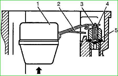
The fuel level in the float chamber is checked once a year with the car installed on a horizontal platform, with the engine not running and the carburetor cover removed.
The fuel level must be within dimension (A) (20-23 mm from the plane of the float chamber connector).
The level is adjusted by bending tongue 4 of the lever of float 1. In this case, the float should be in a horizontal position, and the stroke of valve 3 should be 20-2.3 mm.
The valve stroke is adjusted by bending tongue 2 of the drive lever.
When adjusting the float mechanism, care must be taken not to damage the sealing washer 5.
If the adjustment does not give the desired result, you need to check the carburetor float mechanism.
Usually the causes of high or low fuel levels in the float chamber are a leaking float, incorrect float weight, or a leaking fuel valve.
The tightness of the float is checked by immersing it in hot water with a temperature of at least 80° C and a holding time of at least half a minute.
If the seal of the float is broken, as indicated by the release of air bubbles, the float must be sealed, having previously removed gasoline from it.
After soldering, it is necessary to check its tightness and weight again. The mass of the float assembly with the lever should be no more than 12.5 g.
If the fuel valve is leaking, replace sealing washer 5.
After checking and eliminating the malfunction of the float mechanism, you need to again check the fuel level in the float chamber and, if necessary, adjust it as indicated above.
Adjustment of the minimum speed of the engine crankshaft, the content of carbon monoxide (CO) and hydrocarbons (CH) in the exhaust gases at idle speed is carried out according to the GOST 17.2.2.03-87 method at special posts in motor vehicles or at car service stations ( STO).
The content of CO and CH in the exhaust gases should not exceed:
- - 3.5% CO and 1200 min -1 CH at minimum idle speed
- 20% CO and 600 min -1 CH at increased idle speed
The check should be carried out with the engine warmed up to a coolant temperature of 80-90° C, and with the carburetor air damper fully open.
The check procedure is as follows:
- - let the engine run for 15 seconds. at increased crankshaft speed;
- - reduce the crankshaft speed to minimum idle speed;
- - after 20 seconds. at the established minimum crankshaft speed, check the content of CO and CH in the exhaust gases.
Sharp transitions from one mode to another are not allowed.
Before adjustment, you need to make sure that the ignition system is in good working order, paying special attention to the condition of the spark plugs and the correct gaps between the electrodes, and also for the ZMZ-4025, ZMZ-4026 and UMZ engines, check and, if necessary, adjust the ignition timing at the minimum frequency idle rotation and clearances between rocker arms and valves of the gas distribution mechanism.
The adjustment is made with the engine warmed up to a coolant temperature of 80-90° C.
The adjustment procedure is as follows:
- - remove the restrictive cap from screw 2 of the mixture composition (quality screw).
- - screw 2 and screw 3 for operational adjustment of the idle speed (quantity screw), turn them all the way, but not too tightly, then unscrew screw 3 by 5-6 turns, and screw 2 by 2-3 turns.</ li>
- - start the engine and use screw 3 to set the crankshaft speed (60050) min -1
- - adjust content reduce carbon monoxide and hydrocarbons in the exhaust gases by screwing in screw 2 and maintaining the specified rotation speed with screw 3 to achieve stable engine operation.
In order to ensure optimal engine operation, the plant recommends setting the CO content within 0.5 hours 15% and the CH content - no more than 800 min -1.
- - increase the crankshaft speed to (270050) min -1 and check the content of carbon monoxide and hydrocarbons. In accordance with GOST 17.2.2.03-87, it should not exceed 2% and 600 min -1, respectively.
Exceeding the standards indicates a carburetor malfunction.
- - to check the correctness of the adjustment, press the accelerator pedal and release it sharply.
If the engine stalls, then by slightly unscrewing screw 3, increase the crankshaft speed, but not more than (60050) min -1.
- - after completing the adjustment, place the limiting cap on screw 2.
Its color must differ from the color of the cap set by the manufacturer.
During operation using screws 2 and 3, you are only allowed to make adjustments to the factory settings to obtain the most stable engine operation at the minimum idle speed.
In this case, screwing in screw 2 is allowed only to the angle limited by the movement of the limit cap flag from stop to stop (approximately 270°).
Attempts to rotate the limit cap to a larger angle will lead to its destruction.
Cleaning and flushing of the carburetor should be done on a clean, specially equipped workbench. To perform this work, the carburetor must be completely disassembled, then thoroughly rinse the outer and inner surfaces of the cover, carburetor body, diffusers, throttle body, clean off tar deposits and rinse the fuel, air and emulsion jets, as well as the channels in the carburetor body.
Use unleaded gasoline for flushing.
The carburetor and its parts must be blown out with compressed air after washing.
Rinsing the carburetor with solvents and wiping parts with wiping tips are not allowed.
Cleaning calibrated holes with metal objects is strictly prohibited.
When disassembling and assembling, you must use only serviceable tools to avoid breaking off the splines and crushing the nuts.
The carburetor fasteners should be tightened evenly, avoiding warping of the flanges.
Maintenance of the recirculation system consists of cleaning the holes in the intake pipe with a 4 mm diameter wire and blowing them with the recirculation valve removed after 60,000 km of the vehicle.
Caring for the exhaust system involves periodically tightening all fasteners, especially the connections of the muffler, resonator and exhaust pipe.
Failed muffler, resonator and fastening parts are replaced with new ones.
Caring for the engine mount consists of periodically (every 20,000 km) checking its condition, tightening the mounting brackets and rubber cushions.
To increase the durability of the pillows, it is necessary to ensure that they are not exposed to oil. Failed pillows must be replaced.