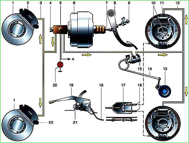
The car has three brake systems:
- - working with a dual-circuit drive (separate braking of the axles), which acts on the brakes of all wheels;
- - spare, the function of which can be performed by each circuit of the working brake system;
- - parking, which acts on the brake mechanisms of the rear wheels.
The service brake system is hydraulic, dual-circuit (divided into front and rear circuits), with a vacuum booster, a pressure regulator and a sensor for an emergency drop in the brake fluid level in the reservoir.
The spare system is formed by each circuit of the working one.
If one of the circuits of the brake system fails, the second circuit provides braking of the vehicle, although with less efficiency.
The parking system is mechanical, with a cable drive from a hand lever to the brake pads of the rear wheels.
The front wheel brakes are disc, with a single-piston floating caliper (when braking, the piston presses the inner pad against the disc, and the caliper, moving in the opposite direction, presses the outer pad).
The minimum permissible residual thickness of the front brake pads is 3 mm.
The discs are ventilated, mounted on the hubs and secured to them with six bolts.
The minimum permissible thickness of a worn disc is 19 mm.
The bracket consists of a base, which is attached with two bolts to the steering knuckle, and a housing connected to the base through guide pins.
The brake cylinder is made in the caliper body; on the outside it is covered with a rubber cover (boot) to protect it from dirt.
Inside the cylinder there is a groove into which an o-ring (cuff) is inserted. When the piston moves out of the cylinder during braking, this ring twists slightly and after braking ends, it tends to return the piston to its original position.
Due to this, a constant minimum gap between the disc and the brake pads is maintained. The cylinder has a valve for bleeding the system.
The rear wheel brakes are drum brakes, with two-piston wheel cylinders and automatic adjustment of the gap between the shoes and the drum.
Thrust rings are inserted into the cylinder with interference, limiting the free movement of the pistons (after braking is completed), thereby maintaining a constant gap between the pads and the drum.
As the pads wear, the rings shift by the amount of wear.
At the top of the brake pads there are eccentrics for adjusting the position of the pads after replacing them.
The minimum permissible thickness of the rear brake pads is 1 mm.
The maximum permissible internal diameter of the brake drum is 283 mm.
The main brake cylinder with a two-section reservoir and a sensor for emergency drop in brake fluid level is attached to the vacuum booster.
The pistons in the cylinder are arranged in series; the one closest to the vacuum booster operates the brakes of the rear wheels, the other piston operates the brakes of the front wheels.
If there are no fluid leaks, its level in the master brake cylinder reservoir should be between the MAX and MIN marks.
As the brake linings wear, the level decreases.
If the brake system leaks, the sensor is triggered and a red warning lamp on the instrument panel lights up. In this case, you can add fluid only after eliminating the malfunction.
The vacuum booster is located between the pedal assembly and the main brake cylinder and is attached to the bracket with four studs.
To increase the braking force, a vacuum is used in the engine intake manifold, to which the booster is connected by a hose.
The amplifier is of a non-separable design; if it fails, it is replaced.
The pressure regulator is attached to the left frame side member.
It adjusts the brake fluid pressure in the rear wheel brake circuit, depending on the vehicle load, which increases the speed stability when braking.
By monitoring the load on the rear axle through a load spring, it limits the fluid pressure in the rear brake circuit.
If the regulator fails, it is replaced.
After replacing the adjuster or rear suspension components, it is necessary to readjust the position of the load spring relative to the rear axle.
Possible brake malfunctions
- Cause of malfunction
elimination method
Increased brake pedal travel:
Presence of air in the hydraulic drive system
Bleed the system
- The thrust ring of the rear wheel cylinder piston has lost its elasticity and, under the action of the tension spring of the brake pads, together with the piston, moves inside the cylinder
Replace the wheel cylinder assembly
- Violation of the tightness of the brake system (fluid leakage)
Locate the location of the fluid leak and replace the parts affecting the leak.
If there is a leak in the pipeline connections, tighten the connections or replace the sealing gaskets
- Increased clearance between the head of the vacuum booster adjusting bolt and the master cylinder piston
See Gazelle vacuum brake booster
The brake pedal moves down slowly with the force on it constant and the parking brake applied:
- Damage to the cuff
Replace the damaged cuff
The brake mechanisms of all wheels or axles are not fully released (the suspended wheels rotate tightly):
- Lack of clearance between the head of the vacuum booster adjusting bolt and the master cylinder piston
See How to replace the vacuum brake booster of a Gazelle car
- Incomplete return of the brake pedal after braking due to incorrect installation of the brake light switch
Set a gap (8+1) mm between the plastic tip of the brake light switch and the pedal stop
- Clogging of the compensation holes of the main brake cylinder or blocking of the compensation holes with the edges of the cuffs
Remove the master cylinder reservoir and connecting sleeves.
Clean the expansion holes with soft wire 0.6 mm in diameter.
If the wire rests against the cuff, then it is necessary to disassemble the master cylinder and replace the swollen cuffs
One brake mechanism does not release (the suspended wheel rotates tightly):
- Jamming of the guide pins at the base of the front bracket
Replace or lubricate the guide pins. Replace damaged finger covers (see Repair of the GAZ-2705 front brake)
- Pistons jamming in the brake caliper body
Remove the brake caliper housing from the base, remove dirt and traces of corrosion from the surface of the housing cylinder and lubricate the working surfaces with NG-213 liquid or castor oil
- Loss of elasticity of the brake caliper housing O-ring
Remove the brake caliper body from the base and replace the O-ring (see How to replace the front wheel brake caliper of a Gazelle car)
- Pads jamming due to severe contamination of the guide groove of the base
Remove the pads and clean the guide groove and ledges of the base from corrosion and dirt (see How to replace the front pads of a GAZ-2705)
- Weakening or breaking of the tension spring of the rear brake pads
Replace the spring
- Seized rear brake pistons due to contamination or corrosion
Disassemble the wheel cylinder, clean the parts from dirt and corrosion, wash, replace the dirt covers
- Swelling of the o-rings of the rear wheel cylinder pistons
Replace O-rings and brake fluid
- Lack of clearance between the brake lining and the rear brake drum due to incorrect installation of the automatic adjustment thrust ring
Disassemble the wheel cylinder, eliminate the distortion of the thrust ring
The car skids or pulls to the side when braking:
- Uneven air pressure in tires
Bring the tire pressure up to normal
- Oiling of the friction linings in one of the brake mechanisms
Replace the pads or wash the linings with gasoline, followed by sanding with fine sandpaper and thoroughly removing abrasive dust from the lining
- Scores or deep marks on the surface of the brake disc or drum
Repair or replace the disc or brake drum assembly with hub
- Brake fluid leak in one of the front brake mechanisms or wheel cylinders
Fix leak
- The rear wheels lock earlier than the front wheels due to a malfunction of the pressure regulator or incorrect adjustment of its drive
Adjust or replace the pressure regulator (see Removal and repair pressure regulator GAZ-2705)
Insufficient braking efficiency (increased force on the brake pedal):
- Worn or oily brake linings
Replace or wash the brake pads
- Incomplete fit of the linings to the drum in the rear brakes
Clean up the protruding areas of the linings. If necessary, replace the pads
- Leak in the vacuum hose connection
Restore the tightness of the connection
- The vacuum brake booster filter is dirty
Wash the filter or replace it with a new one
- The diaphragm of the vacuum brake booster is torn
Replace the diaphragm
- The sealing collars of the vacuum brake booster do not provide a tight seal
Replace the cuffs and clean the cylindrical working surfaces of the valve body and connector
- Violation of tightness in the connection of the cover with the housing of the vacuum amplifier
Restore tightness
- Leakage in the connection between the vacuum booster and the master cylinder body
Replace the O-ring
- Failure of the vacuum booster as a result of brake fluid entering the cavity of the vacuum booster
Replace the master cylinder seals, remove fluid from the amplifier and replace the diaphragm
Rattling in the brake mechanisms:
- Ovality or runout of the working surface of the rear wheel brake drums
Bore the brake drums together with the hub or replace them with new ones
- Breakage of disc brake pad springs
Replace the brake pads
- Wear of the front wheel brake guide pins
Replace guide pins
- Wear of the holes for the guide pins at the base of the brake caliper
Replace base
To hold the car, a lot of force is required on the parking brake handle:
- Sticking of cables in guide shells
Disconnect the cables, clean them from dirt, lubricate the cables and their connections with Liga grease
- Oiling of rear brake linings
Wash the linings or replace the pads with linings
- Parking brake is incorrectly adjusted
Adjust the parking brake drive
Large travel of the parking brake lever handle:
- Large free play of the parking brake drive expansion link in the rear wheel brakes
Adjust the parking brake drive
Heating of brake drums when driving without braking:
- Incorrect adjustment of the parking brake drive expansion link
Adjust the parking brake drive
- - Reduced level of brake fluid in the reservoir of the main brake cylinder in the absence of external leakage in the hydraulic drive
- - Wear or swelling of the outer cuff of the brake master cylinder
Remove the brake master cylinder and replace the cuff.
Drain the brake fluid from the vacuum booster cover