Thermal valve - designed to automatically regulate the oil supply to the oil cooler depending on the oil temperature and its pressure.
On the engine, a thermal valve is installed between the cylinder block and the oil filter.
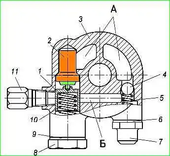
The thermal valve consists of a body 3, cast from an aluminum alloy, two valves: a safety valve, consisting of a ball 4 and a spring 5, and a bypass valve, consisting of a plunger 1, controlled by a thermal power sensor 2, and a spring 10; screw plugs 7 and 8 with gaskets 6 and 9.
The oil supply hose to the radiator is connected to fitting 11.
From the oil pump, oil is supplied under pressure into cavity A of the thermal valve.
When the oil pressure is above 0.7-0.9 kgf/cm², the ball valve opens and the oil enters channel B of the thermal valve body to plunger 1.
When the oil temperature reaches 81 + 2°C, the piston of the thermal power element 2, washed by the flow of hot oil, begins to move plunger 1, opening the way for the oil flow from channel B to the oil cooler.
The ball valve protects the rubbing parts of the engine from an excessive drop in oil pressure in the lubrication system.
To check the technical condition of the thermal valve, disassemble it, rinse its parts in kerosene or gasoline and blow them with compressed air.
Make sure that the thermal valve plunger moves freely in the housing bore without jamming, and that the spring is in good condition.
The mating surfaces of the plunger and body must be free of deposits and burrs, which could lead to jamming of the plunger.
Check the wear of the thermal valve bore and plunger.
Mating parts: thermal valve body - plunger
- Hole – Ø22+0.02 mm
- Shaft – Ø22-0.015-0.045 mm
- Gap – 0.015-0.065 mm
If there is a significant deviation in size from the nominal value, the worn part should be rejected.
The length of the plunger spring in the free state should be 70 mm.
The force on the spring when compressing it to a length of 41.8 mm should be 57.3 ± 10.5 N. If the force is less, the spring should be rejected.
The free length of the safety ball valve spring should be 56 mm. The force on the spring when compressing it to a length of 41 mm should be 7.5 ± 1.5 N. If weakened, replace the spring.
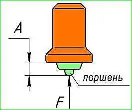
Check the serviceability of the thermal power sensor by the piston protrusion at different temperatures of the oil washing the sensor and the load on the piston created by the spring.
The initial piston protrusion at an oil temperature of (20 ± 15)°C and a piston load of 44.1 ± 4.4 N should be no more than 7 mm.
At a temperature of (95 ± 2) °C and a load on the piston of 113 ± 11.3 N, created as a result of further compression of the spring from 44.1 ± 4.4 N, the piston protrusion must be at least 12.88 mm.
At a temperature of (115 ± 2)°C and the force created as a result of further compression of the spring, the protrusion should be no more than 21 mm.
If the protrusion does not correspond to the given values, the thermal power sensor should be rejected.
Measure the protrusion with a dial indicator with a division value of 0.01 mm. The oil heating rate should not be higher than 1°C/min.
During the test, the oil must be continuously stirred to obtain the same temperature throughout the entire volume.
When assembling the thermal valve, tighten the plunger plug with a torque of 39.2-44.1 N⋅m (4-4.5 kgf⋅m), the ball valve plug with a torque of 24.5-29.4 N⋅m (2.5-3 kgf⋅m), the fitting with a torque of 19.6-49.1 N⋅m (2-5 kgf⋅m), having previously applied "Stopper-6" sealant to the threads of the fitting.
After installation on the engine, warm up the engine to a temperature of 90°C and check the tightness of the thermal valve.
")

")
")
")
")
")
")
")