To monitor the systems, the car is equipped with an instrument cluster in which control devices are installed: voltage indicator, tachometer, speedometer, engine temperature indicator, oil pressure indicator, fuel level indicator and warning lights
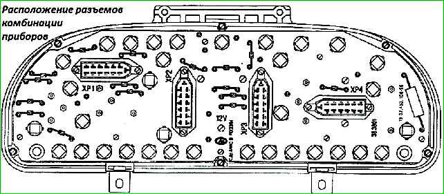
The connection of the instrument cluster contacts is shown in the electrical diagrams, and the location of the electrical connectors is shown in Fig. 1.
To remove the instrument cluster, first remove the trim by unscrewing the four screws.
Then unscrew the four screws securing the combination; disconnect the electrical connectors and remove the instrument cluster.
Repair the instrument cluster by block replacement of faulty devices.
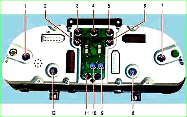
Location of warning lamps and instrument illumination lamps in the instrument cluster of a car manufactured since 2003: 1 - illumination lamp for the coolant temperature indicator; 2 - tachometer illumination lamp; 3 - control lamp for turning on the right turn signal; 4 - signal lamp “STOP”; 5 - control lamp for turning on the left turn signal; 6 - speedometer illumination lamp; 7 - fuel level indicator illumination lamp; 8 - backlight lamp of the first liquid crystal display, displaying the total and daily mileage; 9 - control lamp for turning on fog lights; 10 - indicator lamp for turning on side lights; 11 - control lamp for turning on the high beam headlights; 12 - backlight lamp for the second liquid crystal display, displaying the current time or voltage
To replace devices, remove the protective glass and unscrew the nuts securing the faulty device on the reverse side.
Speedometer
The instrument cluster has an electronic speedometer with a stepper motor.
The speedometer consists of a dial speed indicator, a trip meter and a daily trip meter. The daily counter has a reset button.
The speedometer works in conjunction with an electronic Hall sensor mounted on the gearbox.
When the vehicle is moving, the sensor is driven into rotation by the gearbox secondary shaft gear.
For one revolution of the sensor shaft, 6 pulses of electric current are generated.
These pulses enter the speedometer chip, are converted and sent to a microammeter, which indicates the speed of the car, and to a stepper motor, which rotates the drums of the distance indicators.
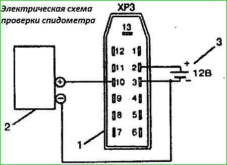
To check the serviceability of the speedometer, it is necessary to assemble the electrical circuit shown in Fig. 3.
Using a G5-54 signal generator, apply rectangular pulses of positive polarity with an amplitude of 6+1 V with a duration of 200-250 μs to pins No. 10 and No. 3 of the HRZ connector.
The accuracy of speed unit readings at control points should be within the following range: 60 km/h - 93.7-100 Hz 100 km/h - 157.2 - 166.6 Hz
The accuracy of the readings of the counting unit is checked using the same principle.
At a frequency of 100 Hz, the “Km/h” drum should rotate by 1 digit in one minute.
The error of the counting unit should not exceed +1%.
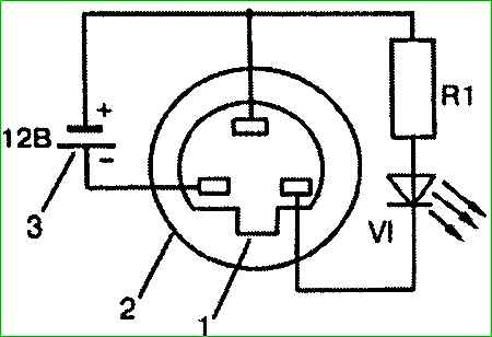
To check the speedometer sensor, assemble the electrical circuit shown in Fig. 4. For one revolution of the sensor roller, the LED should flash 6 times.
Tachometer
An electronic tachometer is installed in the instrument cluster to measure the engine speed.
The tachometer consists of a milliammeter and an electronic circuit.
The alternating voltage from the generator (taken from the stator phase before the rectifier unit) enters the amplifier, then is converted in the microcircuit and enters the milliammeter, the arrow of which indicates the number of revolutions.
The higher the generator speed, the more alternating current pulses enter the electronic part, the greater the angle the tachometer needle deviates.
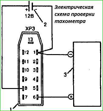
To check the tachometer, assemble the electrical circuit shown in Fig. 5. From the G5-54 signal generator, apply rectangular pulses of positive polarity with an amplitude of 12–2 V and a duration of 200–250 μs to pins No. 1 and No. 6 of the HRZ connector.
At a frequency of 240 Hz, the tachometer should show 1000+100 min -1, and at a frequency of 960 Hz - 4000 min -1 .
Fuel level indicator
The instrument cluster contains an electromagnetic fuel level indicator, which works in conjunction with a sensor installed in the gasoline tank.
The pointer is an electromagnetic ratiometer with fixed measuring coils and a moving permanent magnet.
The magnet is mounted on the axis of the pointer arrow.
The pointer coils are wound at an angle of 90° on a special plastic frame.
The frame with coils and magnet are placed in a special screen to prevent the influence of extraneous magnetic fields on them.
When current flows through both coils, a resulting magnetic field is created.
The permanent magnet, interacting with the magnetic field of the coils, is installed in a position depending on the direction of this field.
The direction of the resulting magnetic field depends on the change in the ratio of currents in the coils, which is determined by the value of the sensor resistance, which in turn depends on the amount of fuel in the tank.
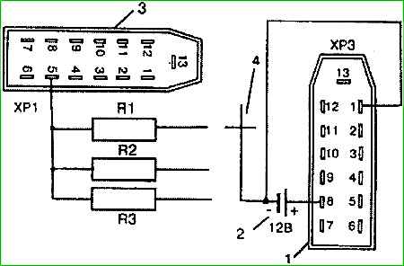
To check the fuel level indicator, it is necessary to assemble the electrical circuit shown in Fig. 6.
When the resistance RI is turned on, the arrow should show “0”, when R2 is turned on - “1/2”, and when R3 is turned on - a full tank.
The deviation of the arrow from the indicated divisions is no more than the width of the arrow.
A working fuel level indicator sensor should have the following resistances: - with the float completely lowered - 330+15 Ohms, and with the float fully raised - 11+5 Ohms.
With an intermediate position of the float 70 mm from the sensor flange to the bottom of the float (measurement is carried out perpendicular to the flange), the resistance should be 118+10 Ohm.
Temperature indicator
In the instrument cluster there is an electromagnetic engine coolant temperature indicator of ratiometric type.
The device consists of a pointer and a sensor installed in the engine. The indicator device is similar to a fuel level indicator, and the sensor is a semiconductor thermistor that sharply changes its resistance depending on temperature changes.
Changing the coolant temperature changes the resistance of the sensor, which causes a change in the current in the pointer coils and the resulting magnetic field rotates the permanent magnet and the needle to the corresponding scale position.
A working sensor at 25°C should have a resistance of 1400-1900 Ohms, and at a temperature of 80°C 200-270 Ohms.
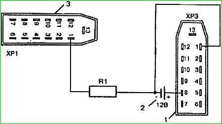
To check the coolant temperature gauge, it is necessary to assemble the electrical circuit shown in Fig. 7.
The indicator arrow should not deviate from the 80°C division by more than the width of the arrow.
Engine overheating indicator
In addition to the cooling system temperature indicator, the vehicle is equipped with an engine overheating indicator.
The sensor automatically turns on the lamp in the instrument cluster when the coolant temperature reaches 104-109° C.
Pressure indicator in the engine lubrication system
To monitor the pressure in the engine lubrication system, a ratiometric-type electromagnetic indicator is used.
The device consists of a pointer located in the instrument cluster and sensor 23. 3839.
The design of the indicator is similar to the fuel level indicator, and the sensor represents is a variable resistance, the value of which changes depending on the position of the membrane, which in turn changes its position depending on the pressure.
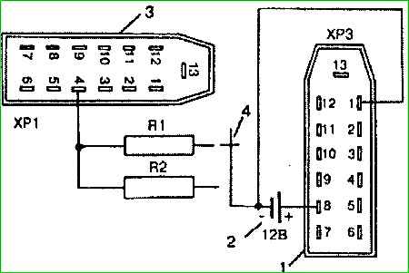
To check the oil pressure indicator, it is necessary to assemble the electrical circuit shown in Fig. 8.
When connecting resistance R1, the indicator should show a pressure of 1.5 kg/cm 2, and when connecting resistance R2 - 4.5 kg/cm 2.
The deviation of the arrow from the specified points is no more than the width of the arrow.
A working sensor should have a resistance of 290-330 Ohms in the absence of pressure, at a pressure of 1.5 kg/cm 2 170-200 Ohms, and at a pressure of 4.5 kg/cm 2 50-80 Ohm.
Indicator lamp for emergency pressure in the engine lubrication system
In addition to the lubricant pressure indicator, there is a signaling device in the instrument cluster.
When the pressure in the engine lubrication system drops from 0.4-0.8 kg/cm 2, the warning light in the instrument cluster lights up.
The alarm works with a sensor type MM111-B.
If there is no pressure in the system, the sensor membrane bends away from the contacts and the lamp lights up, and if there is pressure, the membrane bends in the opposite direction, opens the contacts and the lamp goes out.
Voltage indicator
Ratiometric type voltage indicator, with fixed windings. The voltage indicator device is similar to the fuel level indicator.
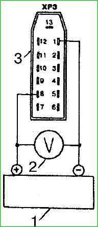
To check the voltage indicator, it is necessary to assemble the electrical circuit shown in Fig. 9.
For monitoring, you must use a voltmeter with a limit of up to 30 V class I and an adjustable direct current source (for example B5-48).
By changing the source voltage, use a control voltmeter to determine the accuracy of the instrument cluster voltage indicator readings.
The error of the voltage indicator at points 12 and 14 V should not exceed +0.4 V.
")

")
")
")
")
")
")
")