Checking the GAZ-2705 switch
Transistor switch type 131.3734 or 90.3734 is installed on the car on the left mudguard behind the battery
It converts the control pulses of the Hall sensor in the ignition distributor into current pulses in the primary winding of the ignition coil.
Since the switch generates a large amount of heat during operation, it is necessary to periodically clean the switch case from dirt and dust and not cover it with foreign objects.
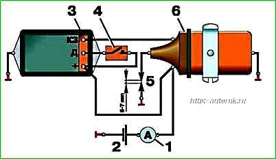
Switch test circuit
- 1 – ammeter;
- 2 – battery;
- 3 – switch;
- 4 – switch;
- 5 – high voltage wire;
- 6 – ignition coil
Execution order
Remove the switch from the car by unscrewing the two fastening nuts and disconnecting the wires.
Assemble the circuit shown in the figure on a suitable metal plate.
Secure the tip of high voltage wire 5 at a distance of 6–7 mm from the plate.
When switch 4 is turned on, ammeter 1 should show a current within 6–7 A, and after 1–3 s the current should drop to 0.
At the moment the switch 4 is turned off, a spark should jump between the tip of the high voltage wire 5 and the plate (permanent sparking is possible).
Otherwise, switch 3 is faulty and must be replaced.
")

")
")
")
")
")
")
")