The brake caliper body is disassembled when replacing pistons, pins, and rubber sealing parts
To disassemble the case you need:
- - disconnect the flexible hose from the brake caliper body;
- - remove the brake pads;
- - remove the brake pads and mark them so that they can be put back in their original place during subsequent reassembly;
- - remove the finger cover from the base;
- - remove the body with the finger from the hole in the base;
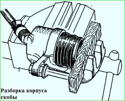
- - install a wooden block 20-25 mm thick between the piston and the body (Fig. 1);
- - push the piston out of the cylinder by connecting a low air pressure hose to the housing inlet;
- - remove the piston boot from the piston groove and remove the piston from the housing, and the boot from the housing groove;
- - remove the sealing ring from the body using a blunt spatula.
After completing these operations, wash all parts with isopropyl alcohol or fresh brake fluid. Do not use gasoline, solvents or other mineral-based liquids for cleaning
Check all parts for wear, damage and corrosion, paying particular attention to the piston working surfaces and cylinder bore.
The edges of the sealing ring must be sharp, without rounding, and the surfaces must be smooth, without tears.
If there is severe corrosion on the working surface of the piston, it must be replaced.
Assembling the brake caliper body
After checking and replacing failed parts, assemble the brake caliper body taking into account the following recommendations:
- before assembly, make sure that the working and sealing surfaces of the housing are clean; lubricate the o-ring with liquid NG-213 TU 38.10.1129-80 and install it in the groove of the housing;
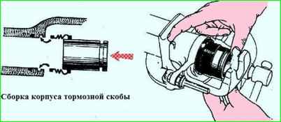
- lubricate the working surface of the piston and boot with NG-213 liquid and install the latter on the piston (Fig. 2).
Without dislodging the cover from the end of the piston, insert it into the groove of the housing;
- - carefully insert the piston with the cover into the housing hole by hand. Place the boot into the piston groove;
- - install the body with fingers into the holes in the base;
- - install the pads in their original place;
- - connect the flexible hose to the bracket body.
Replacement of guide pins must be done in the following order:
- perform operations to remove the brake pads. In this case, you should mark the pads so that during subsequent assembly you can install them in their original place;
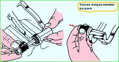
- - unscrew the bolt securing the second guide pin (Fig. 3);
- - remove the finger covers from the base;
- - remove the guide pins from the holes in the base;
- - replace worn guide pins by first lubricating them with UNITOL-1 grease and putting protective covers on them (the covers should not be damaged);
- - perform previously performed operations in reverse order.
Replacing the base
To replace the base you need:
- - disconnect the body from the base (see above);
- - remove the brake pads from the base and mark them so that they can be put in their original place during subsequent reassembly;
- - unscrew the two bolts securing the base to the steering knuckle and remove the base;
- - install a new base on the steering knuckle and tighten the base mounting bolts with a torque of 100-125 Nm (10-12.5 kgf m), having previously cleaned the threaded surfaces of the knuckle and bolts from old sealant and apply fresh Unigerm sealant to the bolts 6" TU 6-01-1285-84.
Proceed with further assembly (see How to replace the caliper brakes of the front wheel of a Gazelle car).
Brake disc repair
The disk is subject to repair if its working surfaces have deep grooves and axial runout of more than 0.1 mm.
The axial runout of the working surfaces of the disk is checked with an indicator when the disk rotates on the hub bearings.
To repair a disk you need:
- - remove the housing and base from the steering knuckle;
- - remove disk from the hub, for which unscrew the bolts with spring washers;
- - grind the working surfaces of the disk based on its end surface adjacent to the hub.
When grinding, it is necessary to ensure a minimum difference in processing between the walls of the disk.
The total tolerance for parallelism and flatness of the working surface of the disk relative to the base surface should be no more than 0.05 mm (which corresponds to the difference in the indicator reading when it moves along the surface being tested), and the total tolerance for parallelism of the working surfaces of the disk with each other should be not less than 0.03 mm.
The thickness of the disk after grinding must be at least 19 mm, and the roughness of its working surfaces must be no more than 1.25 microns according to GOST 2789-73.
If cracks or deep scratches are detected, as well as if the disk thickness is less than 19 mm, the disk must be replaced with a new one.
To do this, you need to install the disk on the hub and tighten the disk mounting bolts with a torque of 44-56 Nm (4.4-5.6 kgf m).
Install the brake caliper housing onto the steering knuckle
")

")
")
")
")
")
")
")