During operation, as well as due to errors in the manufacture of timing gear drive parts or due to unskilled repairs of the timing drive, a significant deviation of the valve timing from the specified values is possible.
The correct valve timing is one of the most important factors affecting the power, torque and economic performance of the engine.
Therefore, when the traction properties of the engine decrease, the operating fuel consumption increases and the engine becomes unstable, it becomes necessary to check and, if necessary, set the valve timing correctly.
For this purpose, a set of equipment developed at ZMZ is used.
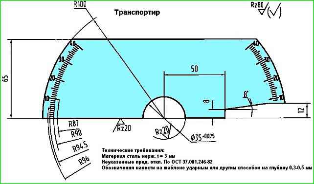
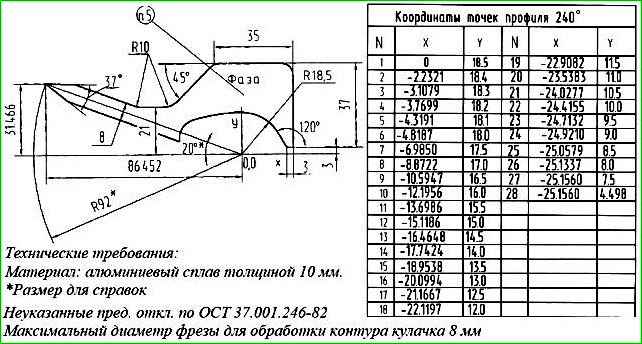
The kit includes: a protractor (Fig. 1), a template (Fig. 2) with a cam profile and an arrow.
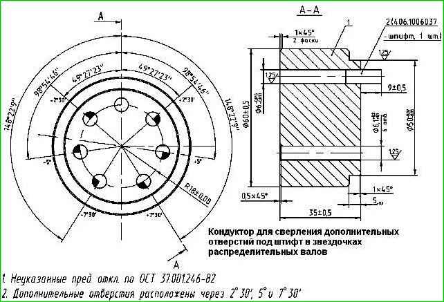
Also a jig for drilling additional holes for the pin in the camshaft sprockets (Fig. 3).
Checking and adjusting the valve timing can be carried out on an engine installed in a vehicle. To check the valve timing, you must:
- Disconnect the crankcase ventilation hose from the valve cover pipe by loosening the clamp.
- Disconnect the wire connectors from the ignition coils.

- Remove the spark plug wire terminals along with the seals and high-voltage wires.
- Release the wiring harness from the brackets and move it away from the valve cover.
- Remove the valve cover assembly with gasket, spark plug well seals, ignition coils and high-voltage wires by unscrewing eight bolts (12 mm socket, extension and ratchet).
Leave the bolts, washers and brackets for the wiring harness in the holes in the cover. (The picture shows the steps using the ZMZ-4062 as an example.)
- Set the piston of the 1st cylinder to TDC of the compression stroke by turning the crankshaft in the direction of rotation (clockwise) until the mark on the crankshaft damper pulley aligns with the indicator rib (a cast boss) on the chain cover.
Attention! Rotating the crankshaft counterclockwise is not permitted.
In this case, the camshaft cams of the 1st cylinder and the marks on the camshaft sprockets must be positioned according to the diagram.
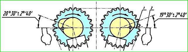
If the cam lobes and marks are pointing inward, then turn the crankshaft one more full revolution.
Precise positioning of the 1st cylinder piston at TDC can be done using a dial indicator, which is installed and secured in the spark plug hole of the 1st cylinder.
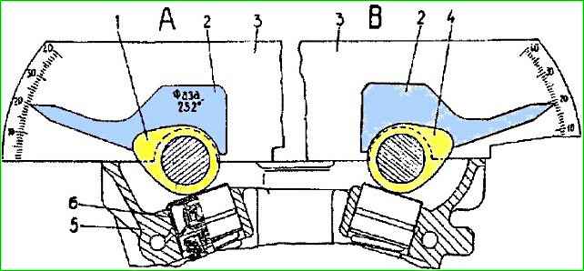
- Install protractor 3 (Fig. 6) behind the first cam of the intake camshaft - view "A", placing it between the cam and the camshaft bearing cap.
While pressing protractor 3 against the upper plane of the cylinder head 5, apply and firmly press template 2 against the surface of the first cam.
The template arrow should align with the protractor mark 20°30′ ± 2°40′.
During measurement, the driving branch of the chain in the area of the upper chain guide (between the camshaft sprockets) must be tensioned and held in this state by turning the intake camshaft counterclockwise with a 27 mm wrench on the square section of the shaft.
Rotating the exhaust camshaft is not allowed during this procedure.
Similarly, check the angular position of the first cam of the exhaust camshaft - view "B".
The template arrow should point to the protractor mark 19°30′ ± 2°40′.
During measurement, the driving branch of the chain in the area of the middle chain guide (between the camshaft sprocket and the intermediate shaft drive sprocket) must be tensioned and held in this state by turning the exhaust camshaft counterclockwise with a 27 mm wrench on the square section of the shaft.
Rotating the intermediate shaft and the crankshaft is not allowed during this procedure.
With these angular position values for the first camshaft cams, the best technical and economic performance of the engine is achieved.
If the deviations in the angular position of the camshaft cams exceed the permissible ±2°40′, adjustment of the valve timing is required.
To do this, perform the following work on the engine:
- Remove the front cylinder head cover by unscrewing the four bolts (12 mm wrench).
- Remove the upper hydraulic tensioner (in the cylinder head) by unscrewing the two bolts (12 mm socket, extension and ratchet) securing the hydraulic tensioner cover. Remove the cover along with the sound-insulating washer.
- Remove the upper and middle chain guides by unscrewing their two mounting bolts each (6 mm hex socket wrench for bolts with a hex socket).
- Remove the camshaft sprockets, unscrewing their retaining bolts one by one (12 mm wrench), while holding the shafts with a 27 mm wrench on the square section of the camshaft.
Prevent the chain, removed from the camshaft sprockets, from jumping off the intermediate shaft sprocket.
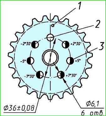
- Using the jig installed on the sprocket, drill six additional holes 3 (Fig. 7) with a diameter of 6.1 mm in each sprocket. These holes should have angular offsets of 2°30′, 5°00′ and 7°30′ from the nominal position of the factory hole 2, which is located on the axis of symmetry of one of the sprocket tooth gullets.
When viewing the sprocket from the side of mark 1, three additional holes offset clockwise from the tooth gullet symmetry axis are positive (+), and the three holes offset counterclockwise are negative (-).
If adjusting the valve timing requires rotating the camshaft(s) in their direction of rotation (clockwise), install the sprocket(s) using one of the additional holes with a positive offset, located to the right of the factory hole. If rotation is required counterclockwise, install the sprocket(s) using one of the holes with a negative offset, located to the left of the factory hole.
Select the hole on the sprocket with the required offset value based on the deviation of the cam's angular position from the nominal value.
When installing the sprocket on an additional hole, the factory alignment mark 1 on the sprocket will not align with the top plane of the cylinder head.
Example
As an example, consider adjusting the valve timing when the template arrow readings are 23°30′ for the intake valve cam and 16°30′ for the exhaust valve cam. These angle values exceed the nominal values for the intake and exhaust cams by 3°, which is greater than the permissible deviation of ±2°40′.
With these angular position readings, and considering that the camshafts rotate clockwise when the engine is running (viewed from the crankshaft pulley side), the intake and exhaust valves will begin to open with some advance relative to the factory valve timing settings.
To adjust the timing in this case, turn the camshafts counterclockwise and, when installing the sprockets, use an additional hole with a negative angular offset of 2°30′ (the first hole located to the left of the factory hole).
Then continue the work in the following sequence:
- Using a 27 mm wrench, turn and set the exhaust camshaft so that the template arrow is opposite the protractor mark 19°30′.
- Place the chain onto the sprocket and orient its first additional hole (located to the left of the factory hole) so that it is positioned in front of the camshaft alignment pin, and the driving branch of the chain (in the area of the middle guide) is tensioned.
To install the sprocket onto the camshaft flange and pin, slightly turn the camshaft clockwise using the wrench on the square section.
After installing the sprocket, turn the camshaft counterclockwise to tension the driving branch of the chain. The arrow of the template installed on the cam should now indicate 19°30′ ± 2°40′.
- Set the intake camshaft so that the template arrow is opposite the protractor mark 20°30′.
- Install the sprocket onto the intake camshaft in the same way as the exhaust camshaft sprocket, using the same additional hole (with negative offset).
With the driving branch of the chain tensioned (in the area of the upper guide), the arrow of the template installed on the cam should indicate 20°30′ ± 2°40′.
- Preliminarily tighten the sprocket mounting bolts (12 mm wrench).
- Disassemble and reassemble ("charge") the hydraulic tensioner. Install it into the bore in the cylinder head, close the cover, tighten the cover bolts, and remove the plug from the cover.
- Through the hole in the hydraulic tensioner cover, press the tensioner with a metal rod or screwdriver until it stops, then release it. This will "discharge" the tensioner: the locking ring on the plunger will disengage from the tensioner body, allowing the plunger and body to move under spring force.
The body will move until it contacts the cover, and the chain will be tensioned via the tensioner lever.
- Screw the plug into the hydraulic tensioner cover, having first applied "Stopper-6" sealant to its threads.
- Check the correctness of the valve timing setting by turning the crankshaft two full rotations in its normal direction of rotation and aligning the marks on the damper pulley and the chain cover.
Perform the check using the protractor and cam template as described above. The arrow of the template installed on the intake cam should indicate 20°30′ ± 2°40′, and on the exhaust cam - 19°30′ ± 2°40′.
If this condition is not met, repeat the valve timing setting procedure.
- Finally, tighten the camshaft sprocket retaining bolts to a torque of 56-62 N⋅m (5.6 - 6.2 kgf⋅m).
- Install the upper and middle chain guides, tightening their mounting screws to a torque of 20-25 N⋅m (2.0 - 2.5 kgf⋅m) (using a 6 mm hex socket wrench for bolts with a hex socket, and a torque wrench with a 6 mm socket).
Apply "Stopper-6" sealant to the mounting screws of the chain guides beforehand.
- Proceed with further engine assembly in the reverse order of disassembly.
After adjusting the valve timing, the engine should run like clockwork.
")

")
")
")
")
")
")
")