The cabin is equipped with supply and exhaust ventilation systems
With natural ventilation, air enters the vehicle interior through lowered door windows and exits through the cracks in the internal panels of the front doors, the sunroof, as well as ventilation windows on the rear side pillars and rear windows of buses.
With forced ventilation, the windows and sunroof are closed, the outside air, without heating, is pumped into the cabin by the heater fan.
Passing through the heater body and bypassing its radiator, the air enters the cabin.
To do this, move the lower handle on the control panel to the extreme left position and turn on the electric fan.
The direction of air flow through the cabin is controlled by rotating nozzles.
Forced ventilation should be used in hot weather at low speeds and in parking lots.
At speeds above 50 km/h, the interior is ventilated with the electric fan turned off, only due to the high-speed air pressure.
The cabin (interior) is heated with hot air.
Passing through a heated heater radiator (included in the engine cooling system parallel to the main radiator), the air is heated and supplied to the passenger compartment.
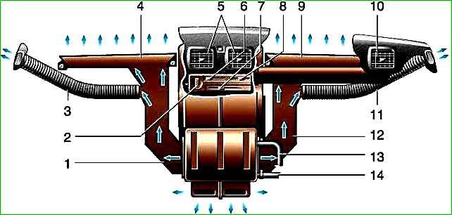
When outside air is taken in, it passes through the grille located between the windshield and the hood, abruptly changes direction and is separated from rainwater, which is drained onto the road through a plastic groove located in the engine compartment.
The air then passes through the air intake duct, the heater itself and (depending on the location of the dampers) is supplied to the windshield, door windows, and also to the driver’s and passengers’ foot area.
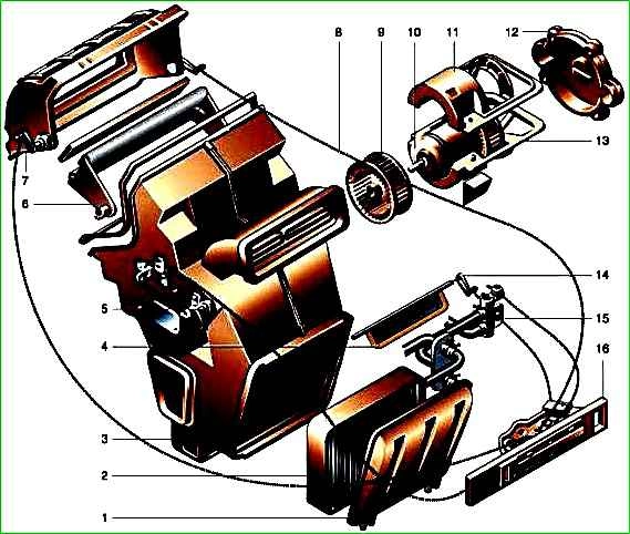
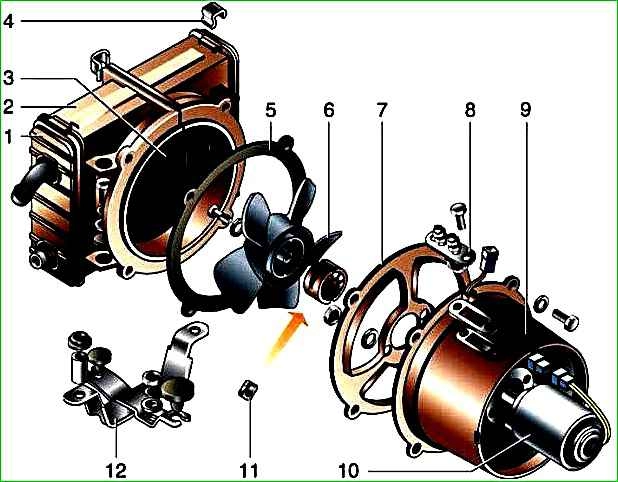
The heater consists of a plastic casing in which a radiator, two fans mounted on the electric motor shaft, upper, central and lower dampers and a control panel with three levers and switches are installed.
An additional resistor is installed on the left side of the heater, providing reduced rotation speeds of the electric fan. The inlet and outlet rubber hoses are suitable for the heater radiator.
Fluid is drawn into the radiator when the heater tap is open, from the cylinder head, and discharged into the engine cooling system pump.
To heat the cabin, by moving the right upper and lower levers of the control panel, open the heater tap, and by moving the dampers we direct the incoming air through the heater radiator.
When the car is moving, air will flow into the cabin even when the fan is turned off. If there is a lack of warm air, as well as in parking lots, we turn on the electric fan.
Turn the switch clockwise to select one of three operating modes of the electric fan.
To increase heating efficiency and, especially, to speed up the heating of the cabin in the cold season, cabin air is recirculated through the heater radiator.
When the upper left lever of the heater control panel is moved to the extreme right position, the upper flap blocks the flow of outside air into the heater and opens the air intake window from the passenger compartment.
The constant circulation of “cabin” air through the heater radiator contributes to its intensive heating.
Redistribution of air flows in the cabin is carried out by the lower lever of the heater control panel.
When the handle is in the extreme left position, the air supply to the heater radiator is blocked and only ventilation occurs she.
In the middle position, air flows to heat the windshield and door windows.
When on the far right, the air is distributed in the same way as the middle position of the handle, plus it additionally flows to the foot area of the driver and passengers.
The upper right lever of the heater control panel is connected to the heater valve and regulates the amount of fluid flowing into the heater radiator.
When the lever is in the extreme right position, the valve is fully open.
Additional heater
An auxiliary heater is installed in the heating system of vehicles with two rows of seats, buses and emergency vehicles.
When the electric fan is turned on, the interior air circulates through the auxiliary heater radiator. This ensures high intensity heating of the cabin (interior).
The auxiliary heater fan has a minimum and maximum rotation speed.
The auxiliary heater radiator is connected to the main heater radiator by hoses. They are laid on the floor and protected by a plastic casing.
The second radiator causes a decrease in the rate of fluid circulation in the heating system.
Therefore, an electric pump is installed together with the additional heater.
It increases fluid flow in the system, which improves heating of the air passing through the heater radiators.
The electric pump is included in the drain line of the heating system and is installed in the engine compartment on the right side member.
It is recommended to use the electric pump when parked and at low engine speeds (travel speed up to 50 km/h).
At high speeds, the engine cooling system pump develops sufficient capacity to circulate fluid through the auxiliary heater.
The additional heater is installed in buses (with a capacity of up to 9 seats), vans with two rows of seats and in the GAZ-32214 car - on the floor, behind the passenger seat of the cab, and in buses with 12 (13) seats - on the floor, in the front parts of the passenger compartment.
To heat the interior of medical modification minibuses, an independent flame-type heater is additionally installed, running on gasoline supplied from the vehicle tank.
The heater can operate while stationary and in motion, regardless of engine operation.