The generator works in conjunction with a contactless transistor voltage regulator 13.3702-01
Voltage regulator 50.3702 can be installed on some vehicles
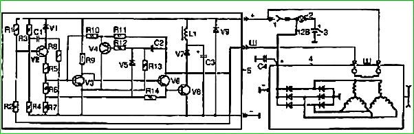
The measuring element of the regulator is a zener diode VI, which controls the transistors.
The output transistor changes the current (average value) in the generator excitation winding circuit and thereby maintains the generator voltage within specified limits.
Technical characteristics of the voltage regulator
The regulated voltage should be 13.8-14.5V at a generator rotation frequency from 2800 to 12,000 min -1, load from 5 to 40 A; temperature from –20 to +80° C.
The voltage drop at the “Ш” and “–” terminals of the regulator at a current of 4 A in the excitation winding circuit and a temperature of 20° C is no more than 1.6 V.
The voltage regulator has protection against possible short circuits in the field winding circuit.
Maintenance and repair
Maintenance of the voltage regulator consists of checking its parameters.
The test can be carried out directly on the car or on a stand.
To check, you must have a DC voltmeter with a scale of up to 20-30 V and a division value of 0.1-0.2 V.
At an average engine speed (1700-2000 min -1), turn on the low beam and measure the voltage in this mode.
The voltage at the “+” terminal of the voltage regulator should be 13.8-14.5 V at a regulator temperature of 20° C.
If, when checking the voltage regulator, the voltmeter reading does not fall within the above limits, the voltage regulator should be replaced.
For the normal operation of the generator and voltage regulator system, the condition of the electrical wiring between the generator, voltage regulator and battery, as well as the reliability of their connection to the housing, is very important.
Therefore, before finding malfunctions in the operation of the generator or voltage regulator, you must carefully check the condition of the specified electrical wiring and the correct connection of the wires.
Defects found during wiring checks (wire breaks, insulation damage, short circuits, dirty tips, etc.) must be eliminated.
The lack of charging current may be caused by the activation of the electronic protection of the voltage regulator in the event of a short circuit in the generator excitation winding circuit.
After the short circuit is eliminated, the operation of the regulator is automatically restored.
Repair and adjustment of the voltage regulator must be carried out by qualified specialists.
To do this, you need an E242 test stand or make a stand equipped with an electric motor for rotating the generator 161.3701 with a smooth change in frequency up to 3000 min -1, a rechargeable battery, a resistor (lamp or wire) to create a current load of up to 20 A and a device for testing semiconductor devices.
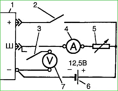
The diagram of the simplest stand for testing the voltage regulator is shown in Fig. 3.
To check, you need to turn on switch 5 and smoothly increase the generator speed to 3000 min -1.
Then turn on switch 6 and use resistor 7 to create a load of 20 A according to current indicator 2.
The voltage adjusted by the regulator will be shown by voltmeter 3.
If, when tested on a bench, the voltage regulator gives an overestimated or underestimated voltage, select resistor R1 (see figure) to achieve an adjustable voltage within 13.8-14.5 V at a regulator temperature of 25° C.
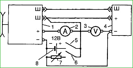
If the regulator does not provide normal excitation of the generator, check the voltage drop at the “Ш” and “–” terminals of the voltage regulator at a current in the excitation winding circuit of 4 A.
The voltage drop should not exceed 1.6 V. Excessive voltage drop Indicates a regulator malfunction.
Before turning on the switch, resistor 5 must have a resistance of 4 Ohms.
After establishing a current of 4 A using current indicator 4, turn on switch 3.
Voltmeter 7 should show a voltage of no more than 1.6 V.
If the regulator does not regulate the voltage of the generator, then first of all you need to check the zener diode, and then the rest of the semiconductor devices.
If the regulator does not provide normal excitation of the generator (no current flows into the excitation winding circuit), then first of all it is necessary to check the output transistor and, if necessary, the others. Faulty semiconductor devices must be replaced.
")

")
")
")
")
")
")
")