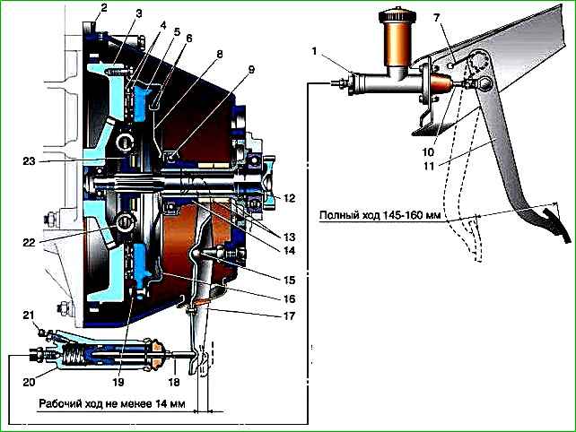
The car is equipped with a dry, single-disk, constantly engaged clutch with a hydraulic drive of the release mechanism
The clutch consists of an aluminum housing, a release clutch with a bearing and a fork, a drive disc assembly (basket), a driven disc, a master and slave cylinders, connected to each other by a hose and tube.
On vehicles equipped with ZMZ-406 and UMZ-4215 engines, only a clutch with a diaphragm spring is installed.
On vehicles with a ZMZ-402 engine, it is possible to install a clutch of both diaphragm and spring-lever type.
The drive disk (basket) consists of a casing in which a diaphragm spring, support rings and a pressure disk are installed.
The spring, attached to the casing, presses on the pressure disk with its edges.
The driven disk consists of a hub with a splined hole and two disks, one of which has leaf springs riveted to it. Friction linings are attached to them on both sides.
Leaf springs with bends contribute to a better fit of the disc and additionally smooth out jerks in the transmission when the clutch is engaged.
For a smoother transmission of torque when starting the car or changing gears, damper springs are installed in the disk windows.
The driven disk is pressed against the engine flywheel by the pressure plate of the basket.
Through friction linings that increase friction, torque is transmitted to the driven disk and then to the input shaft of the gearbox, to which the driven disk is connected by a spline connection.
The clutch release drive is used to temporarily disconnect the engine from the transmission.
When you press the clutch pedal, the piston of the clutch master cylinder moves forward.
The displaced liquid enters the working cylinder through a tube and hose, pushing out a piston with a rod.
The rod acts on the shank of the fork, which rotates on a ball joint, with the other end moving the clutch release clutch along the gearbox bearing cover.
The clutch bearing presses on the ends of the diaphragm spring petals.
Being deformed, the spring stops acting on the pressure plate, which in turn “releases” the driven one, and the transmission of torque stops.
Externally, the clutch mechanism is closed by an aluminum crankcase with a stamped steel pan (lower part of the crankcase) (ZMZ-402, UMZ-4215).
The crankcase is attached to the engine cylinder block with six bolts and two reinforcements. On the other side, four studs are screwed into the crankcase for securing the gearbox.
The crankcase has a seat for the clutch slave cylinder and a window for installing the fork.
To increase rigidity, a reinforcement is installed on the lower part of the clutch housing of the ZMZ-406 engine.
The driven disc differs from the driven disc of a lever-type clutch in the increased dimensions of the friction linings (outer diameter 240 mm, inner diameter 160 mm, thickness 3.5 mm) and parts of the damper device, the number of springs and tension pins, as well as the shape of the leaf springs.
Diaphragm-type clutches are installed in the same crankcases with a lower hatch as lever-type clutches for the ZMZ-4025, -4026 and UMZ-4215 engines, and for the ZMZ-4061 engine - in a solid bell-shaped crankcase.
To install it instead of a lever-type clutch, the mounting holes on the flywheel are located as shown in the figure, and a washer with an outer diameter of 22 mm, an inner diameter of 11 mm and a thickness of 4.5 mm is installed under the ball joint of the clutch release fork.
The housing and pressure plate assembly consists of housing 1, support rings 2, diaphragm spring 3, pressure plate 4 and connecting plates 5.
Clutch casing 1 is secured to the flywheel of the engine crankshaft by six centering special cial bolts.
The force of the pressure diaphragm spring 3 creates the necessary friction force on the surfaces of the friction linings and ensures the transmission of torque from the flywheel through the pressure disk 5, casing 1 and connecting plates 6 to the driven disk and the input shaft of the gearbox.
The pressure diaphragm spring is a disc-shaped truncated cone, which, due to slots in the central and inner parts, has twelve petals that act as clutch release levers.
The outer uncut part of the pressure diaphragm spring is clamped between two support rings 2, 4 by bending twelve antennae made on the casing 1.
When bending them, the pressure spring on a special device must be fixed in a flat state.
The support rings act as a hinge, relative to which the outer part of the diaphragm spring rotates when the ends of the petals are pressed.
The outer part of the diaphragm pressure spring rests on the annular protrusion of the pressure plate and presses it towards the flywheel.
Connecting plates 6 (three groups of three plates in a group) are riveted at one end to the protrusions of the pressure plate, and at the other to the clutch casing.
With their help, torque is transmitted from the casing to the pressure plate and the pressure plate is moved away from the flywheel when the clutch is disengaged.
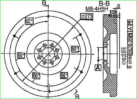
The housing and pressure plate assembly is balanced by installing special balancing weights on the housing flange or by drilling holes with a diameter of 9 mm in the housing flange at a diameter of 273 mm.
The permissible imbalance is no more than 10 gcm. To remove the housing with the pressure plate assembly, it is necessary to remove the clutch housing on the ZMZ-4061 engines or the lower hatch of the clutch housing on the ZMZ-4025, ZMZ-4026 and UMZ-4215 engines.
The housing and pressure plate assembly cannot be repaired during operation; if it fails, it must be replaced.
If there are no visible damages on the casing with the pressure disk: nadir, annular grooves, burns and wear on the working surface of the pressure disk of more than 0.3 mm, wear of the ends of the diaphragm spring petals of more than 0.3 mm, etc., it is necessary to check the location ends of the diaphragm spring petals and its pressing force.
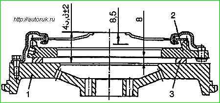
To do this, it is necessary to secure the housing with the pressure disk assembly on the working surface of the new flywheel, placing three evenly spaced 8 mm thick washers between them.
The size from the end of the flywheel to the ends of the petals should be (43.6 ± 2.0) mm.
The deviation from the position in one plane should be within 0.25 mm; if necessary, bend the petals.
When moving the ends of the petals by 8.5 mm, the pressure plate offset must be at least 1.3 mm.
Move the ends of the petals down 10 mm and remove washers 3.
Measure the force at the ends of the petals, releasing them until the distance between the plane of the flywheel and the pressure plate is 6 and 8 mm.
In both cases, the force must be at least 2 kN (200 kgf).
")

")
")
")
")
")
")
")