Replacing the turn signal relay
Depending on the configuration, an electromagnetic relay-breaker of type RS-950P-T or an electronic breaker of type 494.3747, or 642.3747 can be installed on the vehicle
If the RS-950P-T relay fails, we recommend replacing the relay assembly, since if the winding is burned out or the contacts are badly burned, it is difficult to restore its functionality in a high-quality manner.
The design of relays type 494.3747 or 642.3747 is non-separable.
The turn signal interrupter relay is installed on the front panel under the instrument panel on the left side.
Removing relay type 494.3747 or 642.3747

Under the instrument panel on the driver's side, disconnect the connecting block from the turn signal relay

Using a 10mm wrench, unscrew the nut and remove the relay.
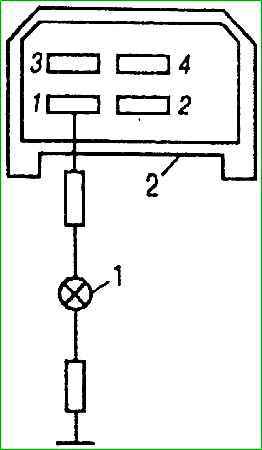
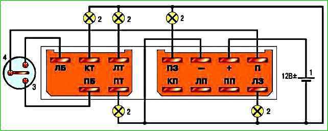
Scheme for checking the presence of voltage in the relay block
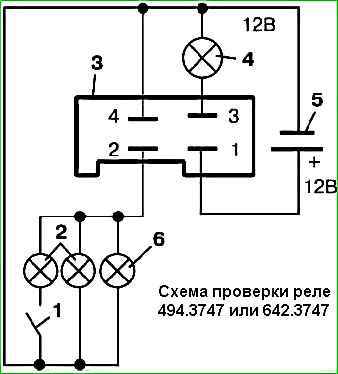
Relay test circuit
Electronic breakers types 494.3747 and 642.3747 do not require maintenance during operation.
These breakers cannot be repaired; if they fail, they must be replaced.
Checking the relay
Install the new relay in reverse order.
Removing and checking relay type RS-950P-T

In order to remove the relay, disconnect the connectors “B” of the wiring harnesses and unscrew the nuts “A”.
To check, remove the RS-950P-T type relay from the car and assemble the circuit (Fig. 1).
If, when the switch is on, the lamps do not light up or are on constantly (not blinking), then inspect the relay contacts
To do this, remove the relay cover. Clean burnt contacts with fine sandpaper, and disconnect stuck contacts.
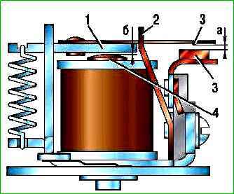
After this, check and, if necessary, adjust the gaps between the contacts.
The gap “a” (Fig. 2) between contacts 3 should be 0.8 mm, and the gap “b” between the relay coil core 4 and armature 1 with contacts 3 closed should be at least 0.15 mm.
In order to adjust the gaps, bend the armature travel limiter 2.
Install the relay in reverse order
Replacing the lamp, removing the front turn signal

From the engine compartment, turning clockwise, remove the socket in the rubber case with the lamp. If necessary, replace the faulty lamp.

To remove the indicator, use a 10mm socket to unscrew the two nuts securing it.

Remove the indicator
Install the front turn signal in the reverse order.
Before tightening the indicator fastening nuts, move it within the slot for the screws, achieving a uniform and minimal gap between it, the headlight and the hood
Replacing the lamp, removing the side turn signal

From the engine compartment, disconnect the socket with the lamp and rubber cover from the turn signal by hand

Remove the lamp from the socket.

Move the turn signal repeater back

Remove the turn signal repeater
Install the side turn signal in the reverse order.
")

")
")
")
")
")
")
")