Headlights include:
- - side light lamps;
- - direction indicator lamps;
- - low beam lamps;
- - high beam lamps;
- - adjusting devices (for initial installation of headlights);
- - electronic-mechanical corrector (for adjusting the angle of the low and high beam depending on the vehicle load).
The side lights and headlights are turned on using the central headlight switch.
Switching the headlights (high-low) and turning on the turn indicators is carried out using the steering column switch.
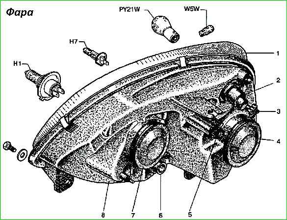
The initial position of the headlights is set using knobs 3 and 5 (Fig. 1).
To adjust the headlights depending on the vehicle load, electronic-mechanical correctors are installed in the headlights, allowing the driver to change the angle of the low and high beam.
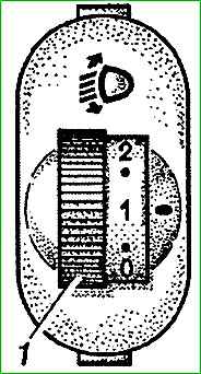
The tilt of the light beam is changed by handwheel 1 (see Fig. 2) of a special electronic unit on the instrument panel.
When the vehicle is unloaded, the number “0” on the control knob should be aligned with the “–” mark on the control unit housing.
When the vehicle is fully loaded, the “–” mark must be combined:
- - number “1” on the handle for buses with 8 (9) passenger seats;
- - number “2” for vans and buses with 12 (13) passenger seats.
Adjust the angle of the headlight beam by changing the position of the headlight reflectors of the electric motor with gearboxes and a tracking system installed in the headlight housings.
When the control unit's handwheel is turned, power is supplied to the electric motors, which, through gearboxes, turn the headlight reflectors to a certain angle.
The angle of rotation of the reflectors is determined and controlled by sensors of the tracking system depending on the position of the control unit.
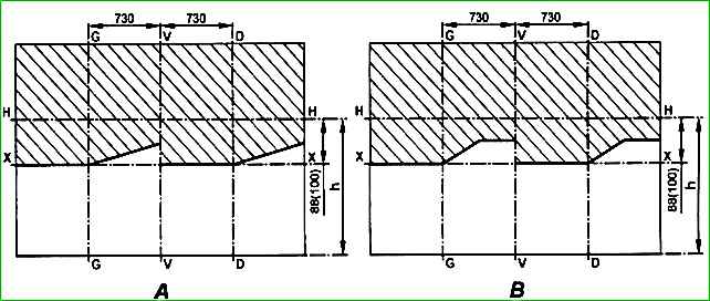
Adjustment of headlights must be done using the screen (Fig. 3) in the following order:
- - check the tire pressure, if necessary, bring it to normal;
- - install an unloaded car at a distance of 5 m from the screen;
- - turn the control knob of the electronic corrector to position “0”;
- - turn on low beam;
- - adjust the light beams with knob 3 (see Fig. 2) and a Phillips screwdriver through socket 5 one by one for each headlight.
For adjusted headlights, the horizontal section of the cut-off line should align with the line X - X (Fig. 3), the inclined sections of the cut-off line should correspond to Fig. 3. “A” (marked on the diffuser “AL”) and fig. 3. “B” (marked on the diffuser “OSVAR”), and the intersection points of the horizontal and the beginning of the inclined sections of the cut-off line - with lines G - G and D - D.
During operation, it is necessary to monitor the serviceability of the lamps. Lamps with darkened bulbs must be replaced.
To replace the low and high beam lamps and clearance lamps, you need to remove covers 4 and 7 - see fig. 2 (on parts of the headlights, these covers can be combined into one.
To remove it, turn the spring holder). To replace the turn signal lamps, turn the lamp socket 2.
- 1. Headlamp lenses marked “OSVAR” are made of plastic, so cleaning them from dust and dirt using various fuels, other active substances and liquids, as well as dry wiping with brushes and rags is unacceptable.
- 2. When installing a halogen lamp in a headlight, do not touch the bulb with your fingers to avoid reducing the luminous flux or destroying the bulb during operation.
Central light switch
Central switch The light has three fixed positions.
When moving the rod, it must be clearly fixed. The force of movement of the rod should be in the range of 10–45 N (1.0–4.5 kgf).
Maintenance
The switch is checked using a test lamp according to the vehicle's electrical circuit diagram.
In positions I and II of the rod and turning it clockwise, lamp 3 should light up;
When the rod is turned counterclockwise, lamp 3 should reduce its brightness and go out when it stops.
The voltage drop at the switch terminals should not exceed 0.01 V at a load of 1.0 A.