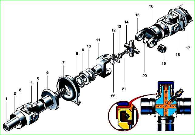
The driveline consists of an intermediate driveshaft, an intermediate support, a rear driveshaft and three universal joints
The intermediate driveshaft is made of thin-walled steel pipe.
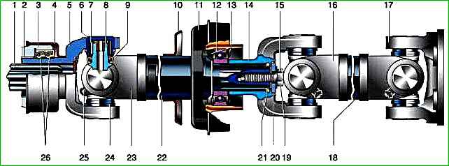
A shank with external splines is welded to the rear end of the intermediate shaft, and a fork is welded to the front end, to which a sliding front fork with an internal spline hole and a mud deflector is attached through a cardan joint.
The front fork (shank) is inserted into the rear transmission housing extension and engages with the splines of the secondary shaft.
When the rear suspension operates, a longitudinal displacement of the cardan transmission occurs. In this case, the shank, moving along the splines of the secondary shaft of the gearbox, compensates for these shifts.
The spline connection is lubricated with oil poured into the gearbox housing.
The intermediate support is a corrugated rubber element; A closed ball bearing is vulcanized to it from the inside, and a bracket is vulcanized from the outside.
The rubber layer prevents the transmission of vibrations to the body and allows the driveline to move along the longitudinal axis of the car. The intermediate support bracket is bolted to the frame cross member.
The support bearing does not require maintenance throughout its entire service life.
The rear propeller shaft is made of a thin-walled pipe, to the ends of which forks are welded.
The splined yoke of the middle joint is attached to the front of the shaft through the cardan joint.
It fits onto the rear spline of the intermediate shaft after the intermediate support.
It is secured against displacement along the splines with a bolt and a lock washer.
A flange with a centering belt is attached to the other part of the rear propeller shaft through the joint crosspiece. It is secured with four bolts to the flange of the main gear drive gear.
The universal joint consists of forks and a cross with four sealed needle bearings. Each of them contains 20 rollers (needles) with a diameter of 2 mm.
The needles are manufactured with high precision, selected for a given bearing assembled with a crosspiece, and are not interchangeable for different bearings.
Therefore, it is unacceptable to replace only the crosspiece or bearings; the entire set is replaced as an assembly, even if at least one bearing is damaged. A grease nipple is screwed into the crosspiece.
From it, oil, pumped by a grease gun, flows through internal channels to the bearings.
Oil retention inside the bearings is ensured by a rubber cuff with a spring.
When the universal joint is “injected”, the spring stretches and excess oil flows out.
Needle bearings are pressed into the coaxial holes of the forks and secured in them with spring retaining rings.
The universal joints of all GAZ vehicles are traditionally lubricated with transmission oil.
This is not very convenient; you have to syringe the connection often. Fill the bearings with grease No. 158 and you can forget about their existence for a long time.
When, when repairing the cardan transmission, you find that the wear on the crosspiece is small and it will still serve, turn it 180˚ around one of the axes of the studs and assemble the hinge in this position.
The spikes will work with the unworn side and the resource of the node will almost double.
Technical characteristics of the cardan transmission
The maximum permissible radial play of the crosspiece bearings is 0.1 mm
The maximum permissible runout of the cardan shaft pipe is 0.6 mm
Runout of the drive gear flange seat - 0.15
Runout of the secondary shaft of the gearbox - 0.15
Possible malfunctions of the cardan transmission
- Cause of malfunction
Remedy
Knock in the cardan transmission when the vehicle moves suddenly or when changing gears:
- Wear of bearings and spikes of crosspieces in hinges
Check the radial clearance in the hinge bearings and, if it exceeds 0.10 mm, replace the crosspiece and bearings
- The shaft is loosened to the rear axle drive gear flange
Tighten the fastening to the specified torque
Vibration of cardan drive:
- Lost balancing plate
Perform dynamic shaft balancing
- The intermediate shaft spline fork is installed incorrectly
Install the splined fork in the same plane as the sliding fork
- The fastening of the intermediate support to the cross member is loose
Tighten the fastening
Increased runout of the sliding fork in the gearbox extension:
- Wear or breakage of one of the hinges
Initially turn the splined fork through an angle of 180° and check to see if the runout decreases. If it does not decrease, replace the worn parts. When replacing a splined fork, dynamically balance the shaft
- Breakage or damage to the rear axle drive gear flange
Replace the hinge
- The propeller shaft pipe is bent or removed
Replace flange
- The shaft fastening to the rear axle is loose
Inspect the shaft, check its runout and, if it exceeds 0.8 mm, straighten it, while its runout should be no more than 0.6 mm at any point along the length.
Balance the shaft dynamically. Tighten the fastening
Faults that are revealed during inspection:
- Rotating the cap with the cuff relative to the bearing cup (violation of the seal of the hinge)
Replace the cross assembly with the bearing. Balance the gear
- Rotating the bearing cup in the fork holes
Replace worn parts, balance the gear
")

")
")
")
")
")
")
")