Replacement of clutch cylinders is mainly associated with the following defects:
- - the clutch does not disengage (the pedal fails);
- - fluid leakage from the cylinder;
- - the clutch slips (the cylinder piston slowly returns to its original position due to swelling of the cuff).
Removing the clutch hydraulic master cylinder
Drain the hydraulic fluid from the hydraulic drive (see How to pump and replace the hydraulic clutch fluid of a gazelle).
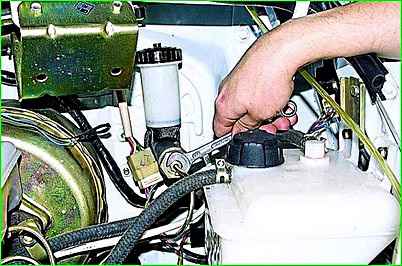
Use a 12mm wrench to unscrew the pipe fitting from the master cylinder.
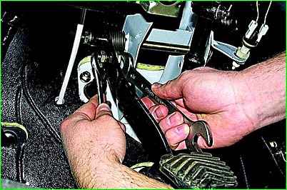
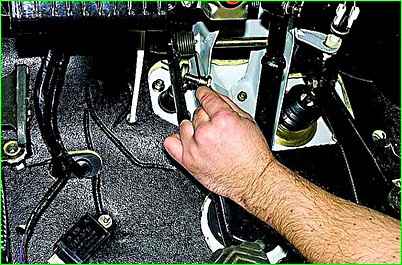
Under the dashboard, holding the rod axis with a 19 wrench, unscrew the nut with a 17 wrench and remove the rod axis along with its plastic bushings.
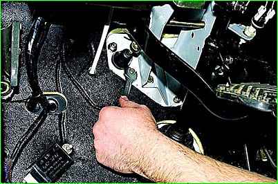
Use a 13mm wrench to unscrew the two nuts securing the master cylinder.
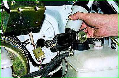
Remove the main cylinder of the hydraulic drive.
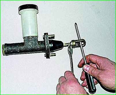
To adjust the position of the clutch pedal and ensure its stroke within the range of 145–160 mm, and the stroke of the operating cylinder rod at least 14 mm, use a large screwdriver and a “13” key to loosen the lock nut, then reduce or increase the length of the cylinder rod by unscrewing or turning the ear.
Tighten the locknut and install the hydraulic drive master cylinder in the reverse order.
Lubricate plastic bushings with any grease
Removing the hydraulic clutch slave cylinder
Drain the working fluid from the hydraulic drive.
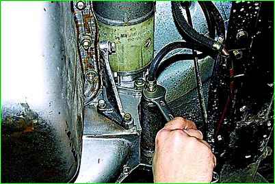
Using a 17 wrench, loosen the tension on the tip of the hydraulic drive hose.
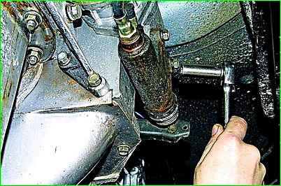
Use a wrench or a 12mm socket to unscrew the two bolts and disconnect the slave cylinder from the clutch housing.
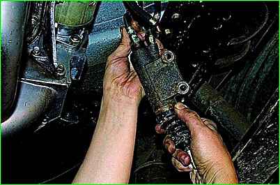
Rotating the cylinder around its axis, remove it from the threaded part of the hose tip.
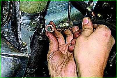
A copper sealing washer is installed under the tip.
Replace the copper washer to ensure the tightness of the hydraulic drive
Install the cylinder in reverse order, making sure that the clutch release fork has not moved from the support.
Fill in fresh working fluid and pump the hydraulic drive.


