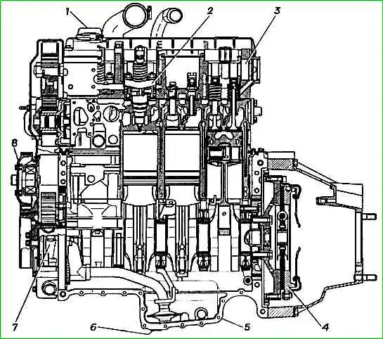
Monoblock - a single one-piece design of the cylinder block and cylinder head without a gas joint
This solution allows you to work with high combustion pressure in the engine cylinders and ensure its high energy performance
This reduces the stress in the upper part of the cylinders and eliminates deformation of the valve seats, which increases the durability of the engine.
Pump injectors - have a mechanical drive and electronic-mechanical control.
Fuel supply is controlled by a microprocessor depending on the crankshaft speed, gas pedal position and signals from sensors installed on the engine.
The advantage of the pump injector is the high fuel injection pressure and, as a result, its better atomization, which makes it possible to provide higher energy performance with less weight compared to similar engines equipped with high-pressure fuel pumps.
Electronic control ensures changes in engine power characteristics depending on driving conditions, as well as constant engine diagnostics.
If an emergency or malfunction occurs in its systems, the fuel supply is reduced or stopped.
Starting the engine in winter conditions is ensured by glow plugs installed in each engine cylinder.
Monoblock - cast, cast iron. And the monoblock houses the blind engine cylinders, gas and air channels, cooling jacket, lubrication system channels and channels supplying fuel to the pump injectors.
Cast iron seats, valve bushings and a copper insert for unit injectors are pressed into the monoblock.
The front support ring of the monoblock is installed in the engine crankcase and consists of an outer aluminum ring and an inner steel ring.
The rings are separated from each other by rubber vulcanized to them.
The front support ring is pressed onto the oil pump housing.
The oil pump assembly with the front support ring is installed on the crankshaft bed and is centered relative to it using installation sleeves.
When installed on a monoblock engine, the front support ring is centered relative to the axis of the crankshaft by two installation sleeves.
The rear support ring of the monoblock is installed in the engine crankcase and consists of 113 two aluminum parts, separated by rubber vulcanized to them.
When installed on the engine crankcase, the ring is centered relative to the axis of the crankshaft by two pins.
Rubber elements on the front and rear carrier rings serve to reduce engine noise.
The crankshaft oil seals are installed in the holes in the rear ring of the oil pump housing.
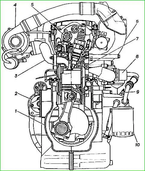
Pistons are made of a special aluminum alloy, with a non-resist cast iron insert under the upper compression ring.
The piston skirt is coated with colloidal graphite.
To maintain normal temperature conditions, the pistons are cooled with oil supplied by an oil nozzle (a jet of oil is directed into the cavity of the piston bottom).
Piston rings. The piston has two compression rings and one oil scraper ring.
Piston pin - steel, floating type, pin movement is limited by retaining rings.
Connecting rod - steel, forged.
The connecting rod is finally processed together with the cap, so the connecting rod caps are not interchangeable.
There are pairing marks on the cover and connecting rod.
A steel-bronze bushing is pressed into the upper head of the connecting rod, stitched after pressing; steel-bronze inserts are installed in the lower head, fixed with a tendril.
Crankshaft of the engine is forged steel.
Main and connecting rod journals are nitrided to increase wear resistance.
To lubricate the connecting rod bearings, oil channels are made in the crankshaft journals.
At the front end of the crank On this shaft, an oil pump drive gear, a camshaft drive gear pulley and a torsional vibration damper combined with the pulley are installed.
The crankshaft is secured against axial movements by four steel-aluminum half-rings installed in the recesses of the fourth main support and secured against rotation using a radial protrusion on the half-ring.
To reduce engine vibrations, the crankshaft is balanced.
Crankshaft bearing shells are three-layer.
The upper and lower shells of the main and connecting rod bearings are not interchangeable.
The upper main bearings are made with a groove and groove, the lower bearings are smooth.
The connecting rod bearings for adjusting the piston clearance are eccentric.
Crankshaft torsional vibration damper with rubber element, non-separable.
Flywheel - cast, cast iron, with a pressed steel gear rim.
Basic data for adjustments and control
The gap between the levers and the backs of the exhaust valve cams on a cold engine at 15 - 20 ° C, 0.3-0.34 mm
The gap between the levers and the backs of the intake valve cams on a cold engine at 15-20° C, 0.15-0.19 mm
Oil pressure (for control, not subject to adjustment), not less, kPa (kgf/cm 2):
- - at idle (at oil temperature 80 -90° C) - (1.0)
- - at nominal speed (3800 rpm) of the engine crankshaft - (5.0-7.0)
Optimal fluid temperature in the engine cooling system, °C 85-95
Minimum crankshaft rotation speed at idle speed, rpm. 850
Deflection* of the belt (between the generator and fan pulleys) of the drive units when pressed with force (4 kgf), 10 mm
Installation stroke of the pump injector plunger, 8.04+0.05 mm (for GAZ-560, GAZ-5601); 8.4 mm (for GAZ-5602)
Stroke of the pump injector plunger to TDC of the piston of the first cylinder, 3.2 mm (for GAZ-560, GAZ-5601) 3.14 mm (for GAZ-5602)
")

")
")
")
")
")
")
")