The engine must be thoroughly cleaned of dirt before disassembly
It is recommended to disassemble and reassemble the engine on a stand that allows the engine to be installed in positions that provide easy access to all parts during disassembly and assembly.
Disassembly and assembly of engines must be done with tools of the appropriate size (wrenches, pullers, devices), the working surface of which must be in good condition.
With an individual repair method, parts suitable for further work must be installed in their original places.
To do this, parts such as pistons, piston pins, piston rings, connecting rods, liners, valves, hydraulic pushers, etc., when removing them from the engine, must be marked in any way that does not cause damage to the parts (punching, labeling, attaching tags and etc.), or place them on racks with numbered compartments, in the order corresponding to their location on the engine.
When using the impersonal method of engine repair, you must remember that the connecting rod caps with connecting rods, the main bearing caps with the cylinder block, the camshaft support caps with the cylinder head are processed as an assembly and therefore cannot be disassembled.
The crankshaft, flywheel and clutch are balanced separately at the factory, so they are interchangeable.
The clutch housing is processed separately from the cylinder block and is also interchangeable. In hydraulic tensioners, disassembly of the housing with the plunger is not allowed.
It is recommended to disassemble the engine in the following order:
- - remove the clutch release fork;
- - remove the gearbox from the engine;
- - remove the fan; - remove the clutch housing and starter;
- - install the engine on a stand for disassembly;
- - loosen the bolts securing the coolant pulley;
- - loosen the bolt securing the tension roller;
- - loosen the belt tension by unscrewing the tension roller moving bolt, remove the belt;
- - unscrew the bolts securing the coolant pump pulley, remove the pulley, pulley reflector;
- - remove the wires with tips from the spark plugs, unscrew the spark plugs;
- - disconnect the high voltage wires from the ignition coil connectors, remove the wires assembled with tips;
- - unscrew the union nuts from the fittings of the intake pipe and exhaust manifold, remove the recirculation pipe;
- - unscrew the valve cover bolts, remove the valve cover assembly with ignition coils, bolts, brackets and washers;
- - remove the fuel line from the fuel pump to the fine fuel filter;
- - remove the fuel pump;
- - remove the front cylinder head cover;
- - remove the upper and middle chain guides;
- - remove the cover with the gasket of the upper hydraulic chain tensioner;
- - remove the hydraulic tensioner;
- - unscrew the bolt securing the intake camshaft sprocket, remove the eccentric and sprocket;
- - remove the drive chain from the camshaft sprockets;
- - remove the sprocket from the exhaust camshaft;
- - unscrew the bolts securing the camshaft covers, remove the covers, thrust flanges;
- - remove the camshafts;
- - remove the hydraulic pushers using a suction cup or magnet, arrange them in order of cylinder numbering;
- - loosen the screws of the intake tract heating hose clamps, remove the hoses from the fittings;
- - loosen the pinch bolt of the upper bracket of the generator;
- - unscrew the nut of the bolt securing the generator to the upper bracket, remove the bolt and bushing; - unscrew the nut of the bolt securing the generator to the lower bracket, remove the generator;
- - remove the recirculation system hoses from the carburetor fittings, thermal vacuum switch, recirculation valve;
- - loosen the screw of the fuel pipe clamp on the carburetor fitting, remove the hose from the fitting;
- - unscrew the carburetor mounting nuts, remove washers, carburetor, gaskets, spacer;
- - unscrew the nuts securing the recirculation valve, remove the washers, valve, gasket;
- - unscrew the bolt securing the fine fuel filter, remove the filter assembly with the fuel pipes;
- - unscrew the thermal vacuum switch;
- - unscrew the nuts securing the intake pipe, remove the intake pipe washers, gasket;
- - unscrew the exhaust manifold mounting nuts, remove washers, exhaust manifold, gaskets;
- - loosen the thermostat housing hose clamps;
- - unscrew the screws securing the thermostat housing, remove the housing, gasket;
- - unscrew the oil pressure sensor fitting;
- - unscrew the cylinder head mounting bolts, remove the bolts and washers; - remove the cylinder head;
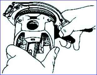
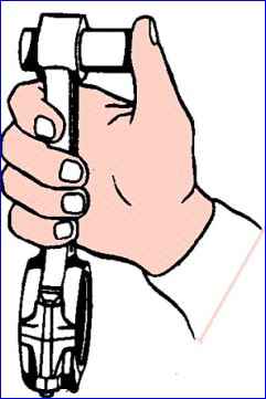
- - use the tool to dismantle the valve springs. In order for the valve spring plate to come off the crackers, after compressing the springs, you need to lightly hit the device plate with the handle of a hammer;
- - remove the valves, arrange them in cylinder numbering order;
- - use a puller to remove the oil seals from the guide bushings. It is recommended to remove the valves when repairing the cylinder head;
- - turn the engine over with the oil sump facing up; - unscrew the bolts securing the clutch housing amplifier to the block, remove the washers, amplifier;
- - unscrew the bolts and nuts securing the oil sump, remove the washers, oil sump, gasket;
- - unscrew the oil pump holder mounting bolt on the third main bearing cover;
- - unscrew the oil pump mounting bolts, remove the oil pump, gasket, hexagonal shaft of the oil pump drive;
- - unscrew the crankshaft pinch bolt, remove the bolt, spring washer;
- - use a tool to remove the crankshaft pulley;
- - unscrew the bolts securing the coolant pump to the chain cover, remove the bolts with washers, coolant pump, gasket;
- - unscrew the bolt securing the tension roller, remove the tension roller;
- - remove the cover and gasket of the first stage hydraulic tensioner, remove the hydraulic tensioner;
- - unscrew the bolt securing the synchronization sensor, remove the sensor;
- - unscrew the screws securing the chain cover, remove the cover, lower generator bracket;
- - remove the chain of the second stage of the camshaft drive from the drive sprocket of the intermediate shaft;
- - loosen the bolts securing the intermediate shaft sprockets, remove the sprockets and chain;
- - unscrew the bolts securing the intermediate shaft flange, remove the bolts with washers, flange;
- - unscrew the bolts securing the oil pump drive cover, remove the cover and gasket;
- - unscrew the nut of the oil pump drive gear, remove the gear assembly with the nut;
- - remove the intermediate shaft;
- - press the key out of the intermediate shaft;
- - use a puller to remove the bushing and sprocket from the crankshaft;
- - unscrew the bolt securing the chain tensioner shoe of the first stage of the camshaft drive, remove the shoe;
- - unscrew the bolt securing the chain tensioner shoe of the second stage of the camshaft drive, remove the shoe;
- - unscrew the shoe bolt extension, remove the extension;
- - unscrew the bolts securing the lower chain guide, remove the guide;
- - unscrew the nuts securing the covers of the first and fourth connecting rods, remove the connecting rod covers with liners, remove the liners from the beds of the connecting rod covers;
- - remove the pistons and connecting rods assemblies from the first and fourth cylinders;
- - install the crankshaft so that the second and third connecting rod journals are in the upper position, unscrew the nuts securing the covers of the second and third connecting rods, remove the connecting rod caps with liners, remove the liners from the beds of the connecting rod covers;
- - remove the pistons with connecting rods from the second and third cylinders;
- - insert a splined mandrel into the splines of the driven disk;
- - unscrew one by one, in several steps, the bolts securing the clutch pressure plate, remove the disc;
- - remove the clutch driven disc with the splined mandrel;
- - loosen the flywheel mounting bolts, remove the flywheel from the pin;
- - unscrew the bolts securing the back cover, remove the back cover assembled with the rubber cuff;
- - unscrew the bolts securing the main bearing caps, remove the bolts;
- - remove the main bearing caps with a puller, the upper crankshaft thrust bearing half washers;
- - remove the crankshaft, lower crankshaft thrust bearing half washers;
- - remove the main bearings from the cylinder block beds and from the main bearing caps;
- - install the main bearing caps into the block according to the numbering;
- - secure the main bearing caps with bolts;
- - unscrew the nut securing the knock sensor, remove the washer, sensor;
- - unscrew the oil filter;
- - unscrew the drain cock from the cylinder block; - remove the connecting rod bearings from the connecting rods; - install the connecting rod caps on the fastening bolts, screw in the nuts;
- remove the compression oil rings from the pistons using a puller; - remove the retaining rings;
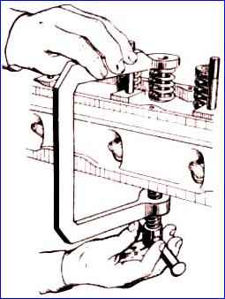
- press out the piston pins from the pistons using a device and a mandrel
Repair of parts, components, assemblies and engine systems
Cylinder block, pistons, connecting rods, intermediate shaft
A cylinder block with holes in the cylinder walls, water jacket and crankcase or with cracks in the upper plane and ribs supporting the main bearings must be replaced.
As a result of wear, the cylinders of the block acquire the shape of an irregular cone in length and an oval in circumference.
Wear reaches its greatest value in the upper part of the cylinders in the area of the upper compression ring, when the piston is at TDC; the smallest - in the lower part, with the piston position at BDC.
When repairing cylinders, two repair sizes are provided: 1st and 2nd. Pistons and piston rings are produced with the same repair dimensions.
All cylinders of the block must, as a rule, be processed to the same repair size with mm deviations established for cylinders of nominal size, with the exception of cases when it is necessary to “remove” shallow scratches on the cylinder mirror (within the limits of increasing the cylinder diameter by 0.10 mm) - in this case, only defective cylinders can be corrected.
If there is a limited number of pistons for repair, it is recommended to calculate the diameter deviations for each cylinder (based on the actual size of the piston skirt diameter intended to work in a given cylinder with a clearance of 0.036-0.060 mm) and bore the cylinders to these dimensions.
Cylinder shape deviations must be within the tolerance range of the dimensional group for the cylinder diameter.
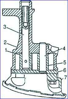
Repair of intermediate shaft support bushings consists of replacing them with repair ones (increased thickness), followed by boring to the nominal or repair size with the tolerance established for supports of the nominal size - depending on the degree of wear of the shaft bearing journals.
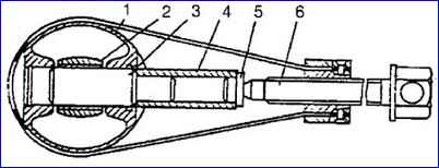
Intermediate shaft: 1 – bolt; 2 – locking plate; 3 – driving sprocket; 4 – driven sprocket; 5 – front shaft bushing; 6 – intermediate shaft; 7 – pipe; 8 – driven gear of the oil pump drive; 9 – ring; 10 – nut; 11 – key; 12 – drive gear of the oil pump drive; 13 – rear shaft bushing; 14 – cylinder block; 15 – intermediate shaft flange; 16 - pin
Before repairing the supports, it is necessary to remove pipe 7
When installing repair bushings, it is necessary to ensure that the holes in the oil channels match. Boring of the intermediate shaft supports is carried out in one installation to ensure alignment.
The intermediate shaft journals are ground to a repair size with the tolerance established for nominal size journals in case of wear exceeding the maximum allowable.
Damage to threaded holes in the form of nicks or thread breakage of less than two threads is restored with a tap to the nominal size.
Threaded holes that have worn or broken threads of more than two threads are restored by cutting threads of an increased size, installing threaded screws, followed by cutting threads of a nominal size into them, or installing threaded spiral inserts. The last method is the most effective and less labor-intensive.
Crankshaft
If there are any cracks, the crankshaft must be replaced.
To remove wear debris in the cavities of the connecting rod journals and in the oil channels of the crankshaft, it is necessary to unscrew the plugs of the journals, flash them (with a caustic soda solution heated to 80° C) and clean the cavities and channels with a metal brush.
After cleaning, they must be washed with kerosene, blown and dried with compressed air, then tighten the plugs with a torque of 38-42 Nm (3.8-4.2 kgf m).
If the thread in holes up to two threads is damaged, it is restored with a tap to the nominal size. If two or more threads are broken, repairs are carried out as follows:
- - threads in the holes for the flywheel mounting bolts - by installing threaded spiral inserts;
- - threads in the hole for the ratchet - by cutting a repair thread; - threads in holes for plugs - by cutting repair threads.
Conrod and main journals, worn within the repair size, are ground to the nearest repair size (1st, 2nd or 3rd) with the tolerance established for journals of the nominal size (all journals are ground to one repair size).
The sharp edges of the chamfers of the oil channels are blunted with a conical abrasive tool, and then the journals are polished.
Cylinder head, valve train and camshafts
If there are holes, burnouts and cracks on the walls of the combustion chambers and destruction of the jumpers between the valve seat sockets, the cylinder head must be replaced with a new one.
Repair of threaded holes is the same as specified for threaded holes of the cylinder block.
To check the tightness of the valves, it is necessary to pour kerosene alternately into the inlet and outlet channels of the cylinder head.
Leakage of kerosene from under the valve plates indicates their leakage.
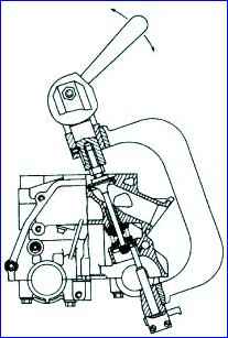
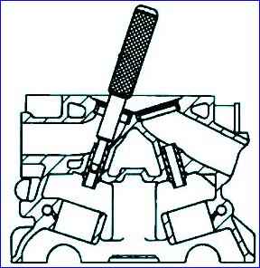
Leaking valves are removed from the cylinder head using a valve spring compressor.
When disassembling, place the valves in the order corresponding to their location in the head, for their subsequent installation in their original places.
Before lapping the valve, you should check for warping of the valve plate and burnout of the valve and seat.
If these defects are present, it is impossible to restore the tightness of the valve by grinding in and the seat must first be bored and the damaged valve replaced with a new one.
If the gap between the valve stem and the guide bushing exceeds 0.20 mm, then the valve and bushing should be replaced with new ones.
For spare parts, valves are produced in nominal sizes, and guide bushings are produced with an allowance for machining along the internal diameter after pressing into the head and with an external diameter of three repair sizes: the first - with an increase of 0.02 mm from the nominal, the second - with an increase by 0.2 mm from the nominal, the third - with an increase of 0.02 mm from the second repair size.
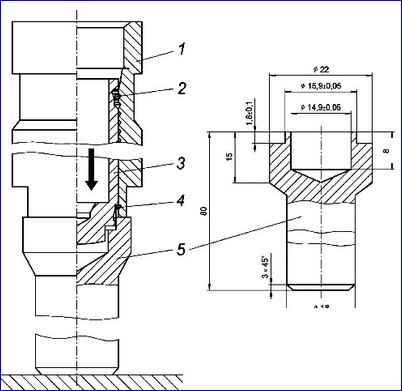
Pressing out a worn guide bushing is done using a mandrel. Before pressing out the guide bushings, it is necessary to determine the maintainability of the cylinder head.
The cylinder head is repairable if, after machining the valve seat, the distance from the camshaft axis to the end of the valve stem pressed against the working chamfer of the seat is at least 35.5 mm.
If this condition is not met, the cylinder head cannot be repaired. The cylinder head also cannot be repaired if the surface adjacent to the block has a non-flatness of more than 0.1 mm.
When installing new guide bushings, they must be cooled in carbon dioxide (“dry ice”) to a temperature of minus 40-45 ° C, and the cylinder head must be heated to a temperature of plus 160-175 ° C.
During assembly, the bushings should be inserted into the head hole freely or with light force.
Bushings of the first repair size are installed in the head without additional machining of the holes in the head, bushings of the second and third repair sizes are installed with preliminary boring (reaming) of the holes to a diameter of 14.2 mm.
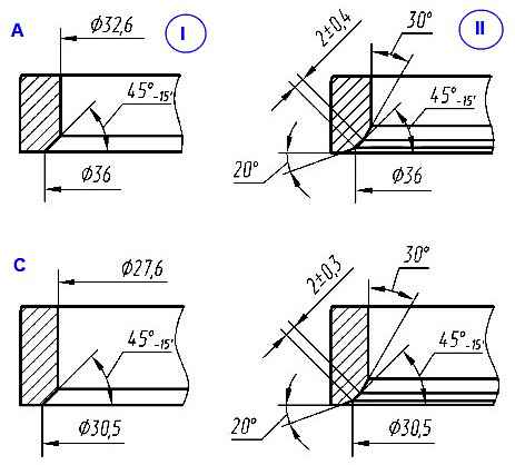
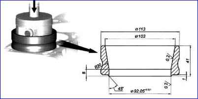
Grinding valve seats: A – intake valve seat; C – exhaust valve seat; I – new saddle; II – saddle after repair
After installing and reaming the bushings, process the seat chamfers (by grinding or boring), centering the tool along the hole in the bushing.
When processing, you should maintain the dimensions indicated in Fig. 7 and ensure that the chamfer on the valve seat is concentric with the hole in the bushing (the runout of the working chamfer of the seat relative to the bushing hole is allowed no more than 0.05 mm).
After processing the chamfers, it is necessary to reduce their width by processing the inner surface of the seats at an angle of 30° to a size equal to (2±0.4) mm for the intake valve seats, (2±0.3) mm for the exhaust valve seats.
Then grind the valves using a lapping paste made up of one part M-20 micropowder and two parts I-20A oil.
Before subassembling the cylinder head, it is necessary to clean the combustion chambers and intake and exhaust channels from carbon deposits and deposits, after wetting the carbon deposits with kerosene, this prevents the spraying of carbon deposits when removing it and prevents the ingress of toxic dust when breathing.
Wipe and blow them with compressed air. On the installed valve guides, it is necessary to simultaneously install the spring support washers using a mandrel and press on the oil seals.
Lubricate the valve stems with engine oil, insert the valves into the bushings according to the order of their installation and assemble them with the springs using a tool.
Make sure that the crackers fit into the annular grooves of the valves. Pour kerosene into inlet and outlet channels and make sure the valves are tight. To determine the clearance in the camshaft bearings, you need to install all bearing caps in accordance with their numbers.
Before installing the cylinder head covers “1”, “2”, “3”, “4”, “5”, “6”, “7” and “8”, they must be lubricated with engine oil.
Centering of these covers is carried out using a cylindrical mandrel with a diameter of 35–0.02 mm, laid in a bed.
After tightening the covers to a torque of 19-23 Nm (1.9-2.3 kgf m), remove the mandrel towards the rear end of the cylinder head (in this case, the rear cover of the cylinder head must be removed).
If the gap in one of the bearings is more than 0.15 mm, then you need to replace either the cylinder head or the camshaft.
The gap in the hole for the hydraulic pusher and the hydraulic pusher should not exceed 0.15 mm. If the gap is larger, either the hydraulic tappet or the cylinder head must be replaced.
The surfaces of the bearing journals and cams must be free of burrs and deep holes and not have wear exceeding the maximum permissible.
After checking the shafts, it is necessary to clean and polish the surfaces of the journals and cams.
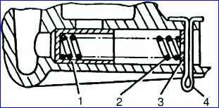
Hydraulic tensioner When repairing an engine, hydraulic tensioners must be disassembled, their parts washed and reassembled (“charged”).
Disassembling the hydraulic tensioner is carried out in the following order:
- - unscrew valve body 1 from hydraulic tensioner body 4; — remove spring 5 and plunger 3 from housing 4.
- The hydraulic tensioner is assembled in the following order:
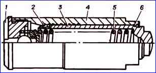
“Charging” the hydraulic tensioner using a mandrel: 1 - housing; 2 – locking ring; 3 - plunger; 4 - retaining ring; 5 - mandrel
- - install the hydraulic tensioner housing 1 on the vertically fixed mandrel 5;
- - insert plunger 3 into the hydraulic tensioner body until the locking ring 4 on the plunger stops in the mandrel belt;
- - press a metal rod with a diameter of 5-7 mm (you can use a screwdriver) on the bottom of the plunger or with your finger on the end of the plunger so that the locking ring from the groove on the plunger moves into the groove of the body (a slight locking click is heard). The body and plunger will be fixed - “charging”. At the same time, the locking ring 2 will enter the first groove of the housing;
- - fill the internal cavity of the body and plunger with clean motor oil used for the engine;
- - insert a spring into the plunger;
- - install the hydraulic tensioner valve on the spring and, compressing the spring, tighten it, and then manually screw it into the body, while the locking ring on the plunger should be in the groove of the body and prevent the plunger from moving in the body;
- - remove the hydraulic tensioner from the mandrel and finally screw the valve into the body with a torque of 19-24 N m (1.9-2.4 kgf m), using a plate 1.8-1.9 mm thick, clamped in a vice, and a key “19”, as when disassembling the hydraulic tensioner.
Coolant pump
Disassembly and assembly of the pump are similar to the specified operations for engines ZMZ-4025, -4026.
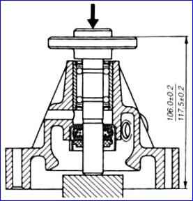
The only difference is that when pressing onto the bearing shaft of the pump pulley hub, the size should be maintained at (106±0.2) mm.
Oil pump If there are malfunctions in the lubrication system caused by malfunctions of the oil pump, it needs to be disassembled.
For disassembly, you must do the following: - bend the wires of the mesh frame, remove the frame and mesh;
Oil pump: 1 - drive gear; 2 - body; 3 - roller; 4 - axis; 5 – driven gear; 6 - partition; 7 - inlet pipe with mesh and pressure reducing valve
- - unscrew the four bolts, remove the intake pipe 7 and the partition 6; — remove the driven gear 5 and the shaft 3 with the drive gear 7 assembled from the housing;
Reducing valve: 1 - plunger; 2 - spring; 3 - washer; 4 - cotter pin
- - remove washer 3, spring 2 and plunger 7 of the pressure reducing valve from the inlet pipe, having previously removed the cotter pin
Preparatory operations before assembling the ZMZ-4061, ZMZ-4063 engines are the same as before assembling the ZMZ-4025, ZMZ-4026 engines.
Assembling the engine must be done in the following order:
- - secure the cylinder block on the stand, carefully inspect the cylinder mirror, if necessary, remove the unworn belt above the upper compression ring with a scraper.
The metal should be removed flush with the worn surface of the cylinder;
- - unscrew the oil channel plugs and blow out all oil channels with compressed air, screw the plugs into place;
Note The crankshaft, flywheel and clutch assembly are not balanced
- - wipe with a napkin the bed under the liners in the block and in the main bearing cover; — install the upper (with grooves) main bearing shells in the block bed, and the lower ones (without grooves) in the cover bed;
- - wipe the liners with a napkin and lubricate them with engine oil;
- - wipe the main and connecting rod journals of the crankshaft with a napkin, lubricate them with clean engine oil and install the shaft into the cylinder block;
- - lubricate with engine oil and install the thrust bearing half washers: the upper ones - in the grooves of the third main bed of the cylinder block (with the anti-friction layer towards the crankshaft cheek); the lower ones - together with the cover of the third main bearing. The antennae of the half washers should fit into the grooves of the cover;
- - install the covers of the remaining supports on the corresponding main journals, screw in and tighten the bolts securing the main bearing covers to a torque of 100-110 Nm (10-11 kgf m), having previously lubricated the bolt threads with engine oil;
- - turn the crankshaft, its rotation should be free with little effort;
- - take the cover with the rubber oil seal at the rear end of the crankshaft, check the suitability of the oil seal for further work. If the oil seal has worn working edges or weakly covers the crankshaft flange, replace it with a new one.
It is recommended to press the oil seal into the cover using a mandrel;
- - fill 2/3 of the cavity between the working edge and the oil seal boot with CIATIM-221 lubricant, install and secure the cover to the block with bolts with a torque of 12-18 Nm (1.2-1.8 kgf m). Center the cover using a mandrel;
- - install the flywheel on the rear end of the crankshaft so that the hole in the flywheel aligns with the pin;
- - install the washer of the flywheel bolts, attach and tighten the bolts to a torque of 72-80 Nm (7.2-8.0 kgf m);
- - install a spacer sleeve into the flywheel and press in the ball bearing 80203AC9 with protective washers.
Perform subassembly of the connecting rod and piston group. The selection of pistons for the block cylinders, as well as piston pins for the pistons and connecting rods should be made at a temperature of the parts (20±3)° C.
Pistons by outer diameter and cylinders by inner diameter are sorted into five size groups.
Pistons of the same size groups as the cylinders must be installed in bored or new cylinders of the block.
Selection from adjacent groups is allowed; in this case, as when selecting pistons for working cylinders, selection is made based on the pulling force of a probe tape 0.05 mm thick and 10 mm wide.
The feeler tape is placed between the cylinder and the piston along the entire height of the piston and is placed in a plane perpendicular to the piston pin axis along the largest diameter of the piston. The force on the dynamometer connected to the probe tape should be 35-45 N (3.5-4.5 kgf).
Piston marking - a letter indicating the group is stamped on the piston bottom;
- the repair enlargement is indicated by the inscription “406” (standard size) or “406AR” (repair enlargement 0.5), or “406BR” (repair enlargement 1.0), cast on the side wall of one of the bosses for the piston pin.
The letter indicating the cylinder group is painted on the outer surface of the block, on the right, opposite each cylinder. For ease of selection, pins, connecting rods and pistons are divided into four size groups in order of decreasing size.
Marking of fingers and connecting rods The fingers and connecting rods are marked with paint: the finger is on the inner surface, the connecting rod is on the head rod. Piston - in Roman numerals (embossed) on the bottom or paint on the weight boss.
The piston pin is matched to a connecting rod belonging to the same or adjacent group with a clearance of 0.0045 to 0.0095 mm.
When selecting, the piston pin should fit tightly, but without jamming, into the hole in the upper head of the connecting rod under the force of the thumb. The piston pin should be lightly lubricated with engine oil.
Since the linear expansion of the piston material is approximately 2 times greater than that of the pin, at normal room temperature the pin fits into the hole of the piston bosses with interference.
The size groups of the piston and pin must match. The piston complete with piston pin, piston rings and connecting rod assembly must be controlled by weight. The difference in weight between sets per engine should not exceed 10 g.
After assembling the pistons and piston pins, it is necessary to continue subassembling the connecting rod and piston group in the following order:
- - clean the piston heads and grooves for piston rings from carbon deposits;
- - press the piston pin into the piston and connecting rod using a tool. In this case, heat the piston to a temperature of 60-80 ° C (pressing a finger into a cold piston can lead to damage to the surface of the holes in the piston bosses, as well as to deformation of the piston itself).
Connecting rods and pistons must be oriented as follows before assembly with the piston pin:
- - the arrow on the bottom of the piston (or the inscription “FRONT” located on the outer side of the pin boss), the ledge on the side surface of the connecting rod cover and the protrusion on the crank head of the connecting rod should be directed in one direction;
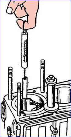
- - select piston rings for the cylinders. The thermal gap, measured in the locks of the rings placed in the cylinder, should be 0.3-0.6 mm for compression rings and 0.5-1.0 mm for steel disks of oil scraper rings.
In worn cylinders, the smallest gap should be 0.3 mm for compression rings and 0.5 mm for steel disks of oil scraper rings;
- - check the gap between the rings and the wall of the piston groove with a feeler gauge. Check the circumference of the piston at several points.
The gap size should be in the range of 0.050-0.087 mm for the upper and lower compression rings, and 0.115-0.365 mm for the assembled oil scraper ring;
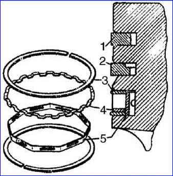
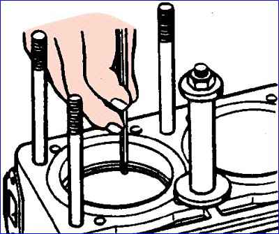
- - put the piston rings onto the piston using the device. Place the lower compression ring with the internal recess upwards towards the bottom of the piston. The rings in the grooves must move freely;
- - insert the pistons into the cylinders as follows:
- - orient the connecting rod-piston group so that the arrow on the piston bottom (or the inscription “FRONT” on the boss) faces forward;
- - wipe the beds of the connecting rods and their covers with a napkin, wipe and insert the liners into them;
- - turn the crankshaft so that the cranks of the first and fourth cylinders take the position corresponding to BDC;
- - lubricate the bearings, piston, connecting rod journal and first cylinder with clean engine oil;
- - move the locks of the compression rings at an angle of 180° to each other, the locks of the oil scraper ring disks are also at an angle of 180° to each other and 90° in relation to the locks of the compression rings.
Insert the lock of the dual-function expander at an angle of 45° to the lock of one of the annular disks;
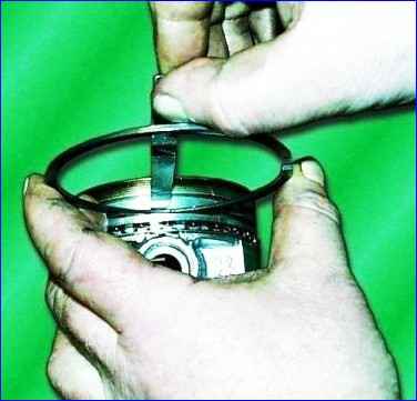
- - put safety brass tips on the connecting rod bolts, compress the rings by crimping or using a mandrel for installation in the piston cylinder;
- - insert the piston into the cylinder. Before installing the piston, you should once again make sure that the numbers stamped on the connecting rod and its cover correspond to the serial number of the cylinder, check the correct position of the piston and connecting rod in the cylinder;
- - pull the connecting rod by the crank head to the connecting rod journal, remove the brass tips from the bolts, and put on the connecting rod cover. The connecting rod cap should be installed so that the numbers stamped on the cap and connecting rod face the same direction. Tighten the nuts with a torque wrench to a torque of 68-75 Nm (6.8-7.5 kgf m);
- - insert the piston of the fourth cylinder in the same order;
- - turn the crankshaft 180° and insert the pistons of the second and third cylinders;
- - turn the crankshaft several times, which should rotate easily with little effort;
- - install the oil pump holder and the oil pump on the block and secure them;
- - lubricate the intermediate shaft bushings with engine oil, install the key in the groove on the intermediate shaft shank and install the shaft into the cylinder block until the shank comes out;
- - install the oil pump drive gear with a nut on the intermediate shaft shank and tighten the gear nut;
- - install and secure the intermediate shaft flange, while the smaller diameter of the hole on the flange should be adjacent to the block;
- - lubricate the shaft with the driven gear of the oil pump drive with engine oil and insert it into the hole in the block until the gears of the oil pump drive engage;
- - insert the hexagonal shaft of the oil pump drive into the hole in the shaft sleeve;
- - install the gasket and oil pump drive cover, secure the cover;
- - install the camshaft drives in the following order:
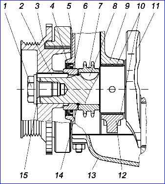
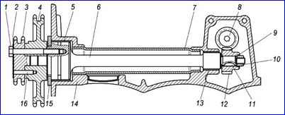
The front end of the crankshaft with a single-groove pulley: 1 - coupling bolt; 2 - parallel key; 3 - damper pulley with a toothed synchronization disk; 4 - cuff; 5 - chain cover; 6 - bushing; 7 - asterisk; 8 – segment key; 9 – cylinder block; 10 - main bearing shells, 11 - crankshaft; 12 – main bearing cover; 13 - oil sump: 14 - rubber sealing ring; 15 - lock washer
- - press sprocket 7 onto the crankshaft shank;
- - install the rubber sealing ring 14 and bushing 6 with a large internal chamfer to the sealing ring on the crankshaft shank;
- - install the crankshaft pulley key into the keyway;

- - turn the engine crankshaft until the mark on the crankshaft sprocket coincides with the “M2” mark on the cylinder block, which will correspond to the position of the piston of the first cylinder at TDC. In this case, the mark on the cylinder block should be located symmetrically relative to the axis of the sprocket teeth cavity;
- - install the lower chain guide 19 without completely tightening the fastening bolts;
- - put chain 6 on driven sprocket 7 (number of teeth - 38) of the intermediate shaft and on sprocket 1 of the engine crankshaft. Install the sprocket with chain on the intermediate shaft, while the mark on the driven sprocket of the intermediate shaft must coincide with the “M1” mark on the cylinder block, and the drive branch of the chain passing through the damper must be tensioned;
- - install drive sprocket 8 (number of teeth - 19) of the intermediate shaft and secure the sprockets to the intermediate shaft with bolts. Bend the locking plate at the edge of the bolts;
- - install shoe 5 of the hydraulic chain tensioner of the first stage (lower chain) of the camshaft drive;
- - while pressing the hydraulic tensioner shoe, tighten the chain, check the correct installation of the sprockets according to the marks and finally secure the lower damper 19.
- After installing the intermediate shaft drive chain, rotation of the crankshaft is not allowed until the camshaft drive chain and hydraulic tensioners are installed;
- - install shoe 9 of the hydraulic chain tensioner of the second stage (upper chain) of the camshaft drive;
- - put chain 11 of the second stage of camshaft drive on the drive sprocket 8 of the intermediate shaft;
- - take the chain cover with the rubber seal and check the suitability of the seal for further work. If the oil seal has worn working edges or weakly covers the crankshaft bushing, replace it with a new one. It is recommended to press the oil seal into the cover using a mandrel;
- - fill 2/3 of the cavity between the working edge and the oil seal boot with CIATIM -221 lubricant;
- - holding the chain second th stage from jumping off the intermediate shaft sprocket, install and secure the chain cover and at the same time the generator bracket, tighten the screws to a torque of 22-27 Nm (2.2-2.7 kgf m);
- - install and secure the coolant pump on the chain cover, tightening the bolt securing the pump to the chain cover to a torque of 22-27 Nm (2.2-2.7 kgf m);
- - lubricate the hole for the hydraulic tensioner in the chain cover with engine oil and install the assembled hydraulic tensioner 2 until it touches the shoe stop, but do not press, in order to prevent the hydraulic tensioner lock from operating; - install a noise-insulating rubber washer 3 into the hydraulic tensioner cover;
- - close the hydraulic tensioner cover and secure it with two bolts;
- - press the mandrel through the hole in the hydraulic tensioner cover onto the hydraulic tensioner, moving it until it stops, then release, in this case the locking ring on the plunger will disengage with the hydraulic tensioner housing and allow the plunger and housing to move under the action of the spring. The body will move all the way to the washer in the cover, and the chain will be tensioned through the shoe;
- - screw plug 4 into the hydraulic tensioner cover;
- - install a hose on the coolant pump pipe connecting the pump pipe to the thermostat housing pipe;
- - apply a thin layer of Elastosil 137-83 adhesive-sealant to the horizontal end of the chain cover and the joint of the chain cover with the cylinder block;
- - install the cylinder head gasket on the block guide bushings and also apply Elastosil 137-83 adhesive-sealant to the surface of the gasket located above the chain cover;
- - install the assembled cylinder head onto the block and tighten the head bolts in two stages - preliminary tightening with a torque of 40-60 Nm (4-6 kgf m) and final tightening - 130-145 Nm (13.0-14. 5 kgf m).
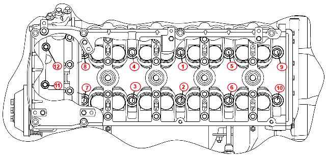
The sequence of tightening the cylinder head bolts is shown in the figure. Lubricate the bolt threads with oil before installation;
- - unscrew the bolts and remove the camshaft covers, wipe with a napkin the bed under the camshafts in the head and in the covers;
- - lubricate the holes in the head for the hydraulic tappets with motor oil used for the engine and install the hydraulic tappets in the cylinder head.
When repairing an engine without replacing the hydraulic pushers, install them in accordance with the markings applied to them during disassembly; if the hydraulic pusher fails, it must be replaced, since it cannot be repaired. The hydraulic pushers must be removed using a suction cup or a magnet;
- - install the camshafts on the cylinder head, having previously lubricated the beds in the head, cams and camshaft bearing journals with engine oil.
The intake camshaft is installed with the sprocket pin pointing upward, and the exhaust camshaft is installed with the sprocket pin pointing to the right. Due to the angular arrangement of the cams, these positions of the camshafts are stable;
- - install the front camshaft cover with the thrust flanges installed in it onto the installation sleeves, and, due to the longitudinal movement of the camshafts, ensure that the thrust flanges are installed in the grooves;
- - install covers No. 3 and No. 7 of the camshafts and pre-tighten the cover bolts until the surface of the covers touches the upper plane of the cylinder head;
- - install all other covers in accordance with the markings and pre-tighten the cover bolts;
- - finally tighten the camshaft cover bolts to a torque of 19-23 Nm (1.9-2.3 kgf m);
- - lubricate all camshaft cams with engine oil and check the rotation of each camshaft in the supports, to do this, turn the camshaft with a wrench using a special tetrahedron on the camshaft until the valve springs of one of the cylinders are fully compressed.
With further rotation, the camshaft should rotate independently under the action of the valve springs until it touches the next cams with pushers;
- - check the ease of rotation of the camshafts and then orient them by turning them so that the alignment pins 13 (see Fig. 22) under the sprockets are approximately horizontal and directed in different directions.
These camshaft positions are stable and are ensured by angular alignment position of the cams;
- - start checking the angular position of the camshafts from the exhaust valve shaft.
To do this, throw the drive chain over the sprocket 16, install the sprocket on the flange and pin of the camshaft, and to align the pin and the hole on the sprocket, turn the camshaft clockwise by the square.
Tighten the drive chain by turning the camshaft counterclockwise, while mark 12 on the sprocket should coincide with the upper plane of cylinder head 17. Do not allow the crankshaft to rotate;
- - for angular installation of the exhaust camshaft, throw the drive chain over sprocket 14, install the sprocket on the flange and the camshaft pin with the chain branch between the sprockets slightly slack.
Tighten the chain by turning the camshaft counterclockwise, so that mark 12 on the sprocket should coincide with the upper plane of the cylinder head;
- - insert the eccentric of the fuel pump drive into the sprocket of the intake camshaft;
- - install and tighten to a torque of 46-74 Nm (4.6-7.4 kgf m) the bolts securing the sprockets (and the eccentric on the intake valve camshaft), holding the camshafts from turning the camshafts with a key by the square;
- - install the hydraulic tensioner 10 of the upper camshaft drive chain in the same way as installing the hydraulic tensioner of the lower chain;
- - install the middle 18 and upper 15 chain stabilizers without completely tightening the fastening bolts;
- - tighten the working branches of the second stage chain by turning the engine crankshaft in the direction of rotation and finally secure the middle and upper chain stabilizers;
- - install the pulley on the crankshaft shank until it stops and screw in the bolt with a torque of 104-128 Nm (10.4-12.8 kgf m);
- - check the installation of camshafts upon completion of assembly. To do this, turn the engine crankshaft two turns in the direction of rotation until the mark on the crankshaft damper matches the mark on the chain cover. In this case, the marks on the camshaft sprockets must coincide with the upper plane of the cylinder head;
- - during engine repairs involving the removal of camshafts, cylinder heads and sprockets on the intermediate shaft, install the camshaft drive during assembly as indicated above;
- - if the intermediate shaft sprockets and chain cover are not removed during repairs, then before disassembling it is necessary to set the piston of the 1st cylinder to the TDC position on the compression stroke, while the mark on the crankshaft pulley must coincide with the protrusion on the chain cover , and the marks on the camshaft sprockets should be located horizontally, directed in different directions and coincide with the upper plane of the cylinder preparation.
After removing the camshafts and cylinder heads, the crankshaft can only be turned by returning to its original position or by 2 turns.
Rotating the crankshaft by 1 revolution, even if the marks on the pulley and the chain cover coincide, will result in incorrect valve timing.
If the camshafts and sprockets are installed incorrectly, the marks on the sprockets will not coincide with the top plane of the cylinder head. In this case, it is necessary to remove the sprockets, turn the crankshaft 1 revolution in the direction of rotation and repeat the installation of the sprockets as indicated above;
- - install and secure the coolant pump pulley;
- - assemble the front cylinder head cover with the intermediate fuel pump drive lever and spring;
- - install and secure the front cylinder head cover;
- - install the thermostat housing pipe into the hose on the coolant pump pipe and secure the thermostat housing to the cylinder head, tighten the hose clamps;
- - install the exhaust manifold, engine lifting bracket and water intake tube bracket onto the exhaust manifold studs, attach and tighten the fastening nuts;
- - press in the oil level indicator rod tube and install the indicator;
- - install and secure the valve cover;
- - install and secure the upper bracket of the generator and at the same time the front engine lifting bracket;
- - install and secure the tension roller;
- - install and secure the inlet pipe;
- - lubricate the joints of the lower flange of the cylinder block with the chain cover and with the rear cover with Elastosil 137-83 adhesive-sealant or UN-25 paste;
- - install the oil pan gasket on the lower flange of the cylinder block;
- - install and secure the oil pan and clutch housing booster;
- - install and secure the driven and clutch pressure plates, centering the driven disc using a mandrel;
- - supply engine parts and assemblies, observing the reverse sequence;
- - remove the engine from the stand, install and attach the clutch housing to the cylinder block;
- - lubricate and place the clutch release clutch assembly with bearing on the front cover of the gearbox;
- - install and secure the gearbox;
- - install the clutch release fork.
")

")
")
")
")
")
")
")