The timing mechanism is driven by a toothed belt 6 from the crankshaft pulley 1
The toothed belt is tensioned by the eccentric bearing of the tension roller 5
The toothed belt is covered with special covers - the bottom cover is aluminum, the top and middle are plastic.
The bottom cover contains the fan drive bearing.
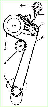
Steel camshaft with cemented cams.
A speed sensor sprocket is installed on the rear end of the camshaft.
A toothed belt drive pulley is installed at the front end.
The valves have a heat-resistant plate welded to the valve stem, the valve stem is chrome plated.
Valve springs are screw with variable pitch.
The valves are driven by lever 2 from the camshaft cam.
The clearance in the valve mechanism is adjusted using an adjusting screw 2 with a ball head through a special hole in the lever.
The adjusting bolt is fixed using a special profile of the threaded insert inside the sleeve 4.
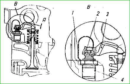
Value A: for intake valves 0.15 + 0.04 mm; for exhaust valves 0.30 + 0.04 mm
Maintenance of the gas distribution mechanism
Maintenance of the gas distribution mechanism consists of periodically checking and, if necessary, adjusting the clearances in the valve drive, as well as checking and, if necessary, tensioning the timing belt of the camshaft drive.
Check and adjust the gaps between the valve levers and the backs of the camshaft cams on a cold engine with the camshaft housing mounting bolts tightened and the tension of the camshaft drive timing belt adjusted.
To check and adjust the clearances in the valve drive you must:
- - provide access to the camshaft housing cover and remove the cover;
- - set the piston of the first cylinder to TDC of the end of the compression stroke, for which turn the crankshaft by rotating the generator pulley with a wrench (if necessary, increase the belt tension by hand, pressing the belt against the pulleys) so that the flat with the number I on the camshaft is directed up, and the mark on the camshaft pulley is aligned with the upper edge of the camshaft housing;
- - use a feeler gauge to check the gaps between the backs of the cams and the valve levers of the first cylinder. For the intake valve, the gap should be 0.15-0.19 mm, for the exhaust valve - 0.30-0.34 mm. If necessary, adjust the gaps by rotating adjusting screw 2 with a TORX key;
- - turning the crankshaft 180° clockwise, check the valve clearances of the third, fourth and second cylinders one by one.
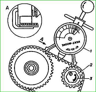
The tension of the camshaft drive timing belt should be within 50±5 daN (50±5 kgf), which corresponds to the green zone of the instrument scale.
Due to the complexity of performing these works and the need to use special tools, it is recommended that the gas distribution mechanism be serviced at a specialized service station (STS).
")

")
")
")
")
")
")
")