Removal and inspection of the driveshaft was discussed in the article - “How to remove the driveshaft of a Gazelle car”
Design features are discussed in the article - “Design and malfunctions of the driveshaft of a Gazelle car”
Disassembling the cardan transmission
Since the cardan transmission is balanced at the factory, each time it is disassembled and subsequently reassembled, it is necessary to maintain the original relative position of the shafts.
Otherwise, noticeable vibration may occur when the vehicle moves.

So that when assembling the splines of the intermediate shaft shank and the splined fork take their previous position, we make marks with paint or a chisel on the intermediate shaft pipe

We make marks with paint or a chisel on the splined fork of the middle hinge.

Use a screwdriver to bend the protrusion of the lock washer located inside the splined fork

Inserting a wrench or screwdriver into the fork, hold the hinge and unscrew the bolt three turns.

Use pliers to remove the U-shaped plate.

Use a copper hammer or use a spacer to knock the fork off the intermediate shaft splines

Remove the bolt with the lock washer

By hitting the splined shank of the intermediate shaft on a wooden lining, we knock down the intermediate support

Remove the protective rings from the intermediate support.

Before assembling the driveshaft, put Litol-24 grease into the recesses of the protective ring on the side facing the driveshaft and insert the ring.
Coat the intermediate shaft splines with CV joint-4 grease.

Using a mandrel made of a pipe (with a diameter approximately equal to the diameter of the inner ring of the intermediate support bearing), we press the support onto the intermediate shaft splines until it stops.

Place grease on the other side of the bearing and put on the second protective ring.
Install the sealing ring into the groove of the rear propeller shaft fork.

We screw the bolt with the lock washer on it into the end of the shaft, having previously lubricated the threaded hole with a few drops of sealant.

After applying a 10 mm wide bead of sealant to the lead-in part of the front shaft splines, we put on the fork, aligning the previously applied marks.

Insert a U-shaped plate under the lock washer so that the protrusion on the plate fits into the cavity of the fork slot, and the antenna on the lock washer fits into the cutout of the plate.
Wrap and tighten the bolt.

Secure the bolt by bending the protrusion of the lock washer onto its edge
Disassembling the universal joint

Having washed the hinge parts with kerosene, we mark their relative position.

Using a screwdriver, carefully remove the bearing retaining rings.

It is more convenient to disassemble the hinge with a special puller.

If it is missing, we press out the bearing in a vice; to do this, we select a thrust ring and a mandrel from sections of pipes or rings of old bearings.

Clamp the hinge in a vice so that the mandrel is located on the side of the oiler and press out the bearings

Having removed the bearings assembled with cuffs from the cross, remove the fork
We similarly press out the second pair of bearings (the cuffs should remain in the bearing housings) and remove the crosspiece.
When installing a new hinge, wash its parts to remove preservative grease.
We wash each bearing separately so as not to mix the needles. The ends of the cuffs should have chamfers; they can be made with a small file.
Having dried the washed parts, we put the cuffs on the spikes of the cross so that the springs face the dirt deflectors.
Pour some oil into the bearing cups and put them on the crosspiece.
Now we remove three of them together with the cuffs, and leave the fourth (from the oiler side).
Further assembly of the hinge is no different from assembling a hinge with used parts.

Insert the free spike of the crosspiece, opposite the oiler, into the eye of the fork, and then the opposite spike with a bearing and a locking ring put on it - into the opposite eye.

We put the bearing on the free spike, inserting it into the hole in the fork eye.

After making sure that both bearings are directed into the fork holes, we clamp the hinge in a vice, placing a thrust ring between the vise jaw and the fork eye.

Press in the bearing on the oiler side until the lock washer touches the fork eye.
Place the second locking ring on the opposite bearing.
Assemble both halves of the hinge in the same way, but do not forget to restore the relative position of the forks according to the marks made before disassembly.
When assembling the remaining hinges, install the crosspieces so that the oil nipples of all hinges are located in the same plane and on the same side of the hinge.
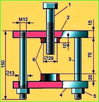
Unit for disassembling cardan joints
Disassembling any universal joints will be easier and more convenient if you use the device shown in the figure.
The distance between the support plates is selected depending on the dimensions of the hinge.
")

")
")
")
")
")
")
")