The engine has a closed crankcase ventilation system, operating due to vacuum in the intake pipe and air filter
The diagram of the crankcase ventilation system is shown in the figure
When the engine is running at low loads and at idle, gases from the crankcase are sucked through a calibrated hole with a diameter of 2 mm in the carburetor throttle body through pipeline 2 into the intake pipe.
In other engine operating modes, most of the gases are discharged through pipeline 1.
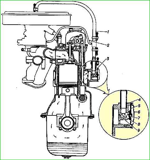
To separate oil droplets (suspended in crankcase gases) and to reduce the entry of dust and dirt into the engine crankcase when the vacuum in the intake system increases, for example when the air filter is clogged, a crankcase vacuum regulator is installed, located in the front cover of the box pushers.
When the vacuum in the intake system increases, the membrane with the shut-off valve 7, under the influence of vacuum, overcoming the force of the spring 8, moves towards the valve seat 7, blocking the inlet to the spring seat, thereby reducing the consumption of crankcase gases and maintaining an optimal vacuum in the crankcase.
When the inlet hole into the spring seat is completely blocked, gases from the crankcase flow only through calibrated hole 9.
Maintenance of the ventilation system consists of cleaning the pipelines (hoses) and calibrated hole 9 and washing the parts of the vacuum regulator.
For washing and cleaning, the vacuum regulator must be removed from the engine and disassembled.
When assembling the vacuum regulator, it is necessary to ensure the tightness of the connection between the housing and the cover.
During operation, do not break the tightness of the crankcase ventilation system and do not allow the engine to operate with the oil filler neck open - this causes an increased release of toxic substances into the atmosphere.
With the engine running and the ventilation system in working order, there should be a vacuum in the crankcase within 10-40 mm of water column, which can be determined using a water piezometer connected to the oil level indicator socket on the cylinder block.
If the system is faulty, there will be excess pressure in the crankcase.
This is possible in the case of coking of the ventilation channels, due to significant wear of the cylinder-piston group, which causes excessive breakthrough of gases into the engine crankcase.
Increased vacuum in the crankcase (more than 50 mm of water column) indicates a malfunction of the vacuum regulator.
In this case, it is necessary to wash the parts of the vacuum regulator and clean hole 9.
")

")
")
")
")
")
")
")