A typical electrical circuit may include a main electrical element, various switches, relays, electric motors, fuses, fuse links or circuit breakers, wiring and contact connectors related to this element, which serve to connect the main element to the battery and the body "ground"
Before you begin troubleshooting any electrical circuit, carefully study the corresponding diagram in order to understand its functional purpose as clearly as possible.
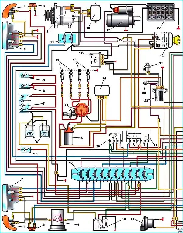
Scheme 1. Electrical equipment of GAZ-2705 vehicles with ZMZ-4025 and ZMZ-4026 engines: 1 - direction indicator; 2 headlight; 3 direction indicator repeater; 4 windshield washer motor; 5 hood lamp; 6 rear seat light (for vehicles with two rows of seats); 7 cabin light; 8 cargo compartment light; 9 generator; 10 voltage regulator; 11 fuse box in the engine compartment; 12 Starter relay; 13 Spark plug; 14 Transistor switch; 15 - Ignition distributor; 16 Ignition coil; 17 - Lower fuse box; 18 - Rear seat lamp switch (for vehicles with two rows of seats); 19 Horn; 20 Rear fog light switch; 21 - Central light switch; 22 Idle speed control unit; 23 Idle speed control system switch; 24 - Solenoid valve; 25 Ignition switch (lock); 26 Starter; 27 - battery;
The troubleshooting circle is usually narrowed by gradually identifying and eliminating normally functioning elements of the same circuit.
If several elements or circuits fail at the same time, the most likely cause of the failure is the burnout of the corresponding fuse or a violation of the contact with the "ground" (different circuits in many cases can be shorted to one fuse or ground terminal).
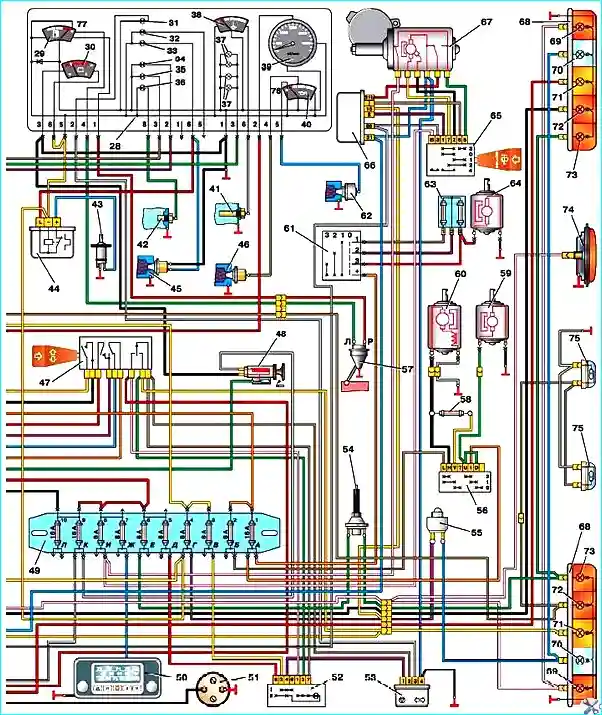
Scheme 2. Electrical equipment of GAZ-2705 vehicles with ZMZ-4025 and ZMZ-4026 engines: 28 - instrument cluster; 29 fuel tank level indicator; 30 voltmeter; 31 turn signal indicator lamp; 32 reserve lamp; 33 brake fluid level emergency warning lamp; 34 high beam indicator lamp; 35 parking light indicator lamp; 36 coolant overheating indicator lamp; 37 instrument backlight lamp; 38 coolant temperature indicator; 39 tachometer; 40 oil pressure indicator; 41 coolant temperature indicator sensor; 42 Coolant overheating warning lamp sensor; 43 Parking brake warning lamp switch; 44 - Parking brake warning lamp flasher; 45 - Brake fluid level warning lamp low sensor; 46 Oil pressure indicator sensor; 47 Direction indicator switch; 48 Cigarette lighter; 49 Upper fuse box; 50 Radio; 51 Portable lamp socket; 52 Hazard warning lamp switch; 53 Direction indicator flasher; 54 - Brake signal switch; 55 Reversing light switch; 56 Auxiliary heater motor and heating system electric pump switch (for vehicles with two rows of seats); 57 Fuel tank gauge sensor; 58 Auxiliary heater motor resistor (for vehicles with two rows of seats); 59 - Heating system electric pump (for vehicles with two rows of seats); 60 Additional heater motor (for vehicles with two rows of seats); 61 Heater motor switch; 62 Oil pressure warning light sensor; 63 Heater motor resistor; 64 Heater motor; 65 Windscreen wiper switch; 66 Windscreen wiper relay; 67 Windscreen wiper motor; 68 Tail light; 69 Fog light; 70 Reversing light; 71 Parking light; 72 Turn signal; 73 Brake light; 74 Additional fog light; 75 Sign; 76 Oil pressure warning light; 77 Minimum fuel reserve in tank License plate light Minimum fuel reserve warning light
Electrical equipment failures are often explained by simple reasons such as corrosion of connector contacts, a blown fuse, a blown fuse link or a damaged relay.
Visually inspect the condition of all fuses, wiring and connectors in the circuit before proceeding to a more detailed check of the serviceability of its components.
")

")
")
")
")
")
")
")