Generator 1601.3701 – three-phase synchronous electric machine with electromagnetic excitation and built-in rectifier using silicon diodes
The generator is installed on cars with a ZMZ-402 engine.
The generator rotor is driven by a V-belt from the engine crankshaft pulley.
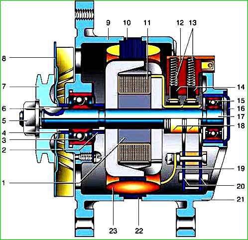
The stator and generator covers are secured with four screws.
The rotor shaft rotates in ball bearings installed in the covers.
The bearings are lubricated for the entire service life of the generator.
The rear bearing is pressed onto the rotor shaft and is pressed by the rear cover through a plastic sleeve.
The front bearing is installed on the inside of the front cover and is secured with a washer and four screws.
The generator stator has two three-phase windings, made in a star configuration and connected in parallel to each other.
Bridge circuit rectifier, consists of six diodes.
They are pressed into two horseshoe-shaped aluminum holder plates.
The plates are combined into a rectifier unit mounted inside the back cover of the generator.
The generator excitation windings are located on the rotor.
The winding leads are soldered to two copper slip rings on the rotor shaft.
Power is supplied to them through two carbon brushes installed in the brush holder.
The generator works in conjunction with a voltage regulator, which is mounted on the front panel in the engine compartment.
If the regulator fails, it is replaced.
To protect the vehicle’s electronic equipment from voltage pulses in the ignition system, as well as to reduce radio interference, a capacitor is connected between the “+” and “ground” of the generator.
The internal windings of the generator and the rectifier unit are cooled by air through windows in the covers from a centrifugal fan mounted on the rotor shaft.
Technical characteristics of generator 1601.3701
Nominal voltage 14 Volts;
Maximum current 65 A;
Adjustable voltage 13-15 V;
Excitation winding resistance 2.3-3.7 Ohm
Removal and repair of the generator
Disconnect the battery.

Disconnect the plug block from the generator brush holder.

Use a slotted screwdriver to unscrew the screw and release the clamp securing the wires to the generator.

Use a 10mm wrench to unscrew the nut and disconnect the wires from the generator.

Using a 12mm wrench, unscrew the bolt securing the generator to the tension bar

Remove the bolt together with washers.

Using a 13mm wrench, loosen the nut securing the bar to the cylinder head (for clarity, the cooling system hose has been removed).

From the bottom of the car, using a 14mm wrench, sequentially hold the bolts of the lower mounting of the generator, and using a 17mm wrench, unscrew the nuts

Lifting the generator up, remove it from the engine

Use a 10mm wrench to unscrew the contact bolt nut.

Unscrew the fastening screw and remove the capacitor.

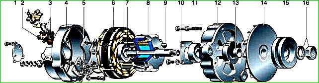
Remove the four screws holding the generator covers together.

Using a screwdriver, remove the back cover assembled with the stator.

If it is not possible to disassemble the generator in this way, unscrew the three screws securing the bearing cover.

Holding the generator by the stator, carefully press the back cover with a hammer through a soft metal mandrel.

Use a 10mm wrench to unscrew the three nuts securing the terminals

Remove the stator from the cover.

Use a 10mm wrench to unscrew the nut

Having removed the insulating washer, remove the contact bolt.

Remove the three screws securing the rectifier unit to the cover

Having removed the block, remove the insulating sleeve.

Remove the plastic bearing bushing from the back cover of the generator.

Remove two washers.

Baiting nut onto the threaded part of the rotor shaft flush with the end.
Hold the generator suspended by the impeller and knock out the pulley with light blows of a hammer through a soft metal drift

After unscrewing the nut, remove the pulley and impeller.

Use a thin chisel or beard to knock out the key

Remove the thrust bushing

If there is no special puller, screw the nut onto the shaft flush with the end and use a hammer to knock the shaft out of the bearing using a soft metal drift.

Use a screwdriver to unscrew the four screws securing the front bearing cover

Remove the cover

Knock out the bearing through the mandrel

Installing a new bearing.

We press it through a mandrel or a “36” head.

Use a puller to remove the rear bearing from the rotor shaft.

Press in the new bearing with a suitable bushing, applying force to the inner ring

Using an ohmmeter we check that there is no short circuit of the stator winding to the housing

Check for an open circuit in the stator winding

Check that the rotor winding is not shorted to the housing.

We measure the resistance of the rotor field winding, which should be in the range of 2.3–2.7 Ohms.

Applying voltage (12 V) of different polarity to the diodes, we check the serviceability of the rectifier unit
We replace the faulty rotor and stator
The valves of the rectifier block have one-way conductivity. A faulty one, as a rule, passes current in both directions.
Replacement of individual valves is possible, but they will need to be repressed into the holder - operation an activity that requires accuracy and skill.
Therefore, if its elements fail, we recommend replacing the rectifier unit as an assembly.
Before assembly, clean the parts from dirt, oil and coal dust.
Assemble the generator in reverse order
")

")
")
")
")
")
")
")