Checking and adjusting valve thermal clearances
For adjustment you need:
- - disconnect the crankcase ventilation hoses
- - remove the rocker cover;
- - remove the radiator grille, disassemble
Checking and adjusting the thermal clearances between the valves and rocker arms is carried out on a cold engine with the cylinder head fastening nuts and the rocker arm axle mounting nuts tightened.
To check the air filter, disconnect the throttle valve drive cable and the hose of the vacuum regulator of the sensor-distributor;
- - fastening the upper mounting point of the radiator, remove the top panel of the radiator trim and loosen the tension of the fan drive belt;
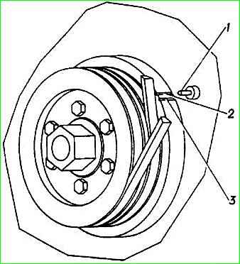
- set the piston of the first cylinder to the top dead center (TDC) of the compression stroke, for which, using a special 36 mm wrench from the driver’s tool kit, turn the engine crankshaft to a position at which the rocker arms of the intake and exhaust valves swing freely (valves are closed) , and the second mark on the damper pulley will align with the pin on the timing gear cover;
The first mark is the one that approaches the pin when rotated clockwise.
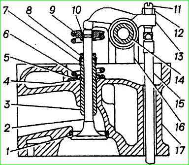
- use a feeler gauge to check the gaps between the rocker arms and the valves of the first cylinder.
If the gap is incorrect, use the adjusting screw to set the gap using the feeler gauge, then, supporting the adjusting screw with a screwdriver, tighten the lock nut and check the correct gap;
- turning the crankshaft half a turn, adjust the clearances of the remaining cylinders according to their operating order 1-2-4-3.
The gap between the rocker arm and the valve on a cold engine (15-20° C) for the exhaust valves of the first and fourth cylinders should be 0.30-0.35 mm, and for the remaining valves - 0.35-0.40 mm.
The first cylinder is counted from the car radiator
More details:
The clearances are adjustable on a cold (15-20°C) engine.
The gap values should be 0.30–0.35 mm for the exhaust valves of the first and fourth cylinders (outer valves). For all other valves – 0.35–0.40 mm.
Remove the cylinder head cover.
Using a 36mm socket or wrench, turn the crankshaft by the damper pulley mounting bolt clockwise (front view)…
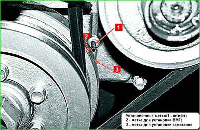
... until the second (clockwise) mark on the damper pulley aligns with the timing gear cover pin (the piston of the first cylinder must be at TDC on the compression stroke - both valves are closed).
If the valves do not close (exhaust stroke), turn the crankshaft one more revolution.
Using a set of feeler gauges, we check the clearances in the valve drive of the first cylinder.

Using a 14mm wrench, loosen the locknut of the adjusting screw and unscrew the adjusting screw one or two turns.
Insert a feeler gauge between the valve stem and the rocker arm.
Turn the adjusting screw until the feeler gauge moves in the gap with little force.

Having set the gap, hold the adjusting screw, tighten the locknut (the gap will decrease slightly) and check the gap again.
Adjust the clearances of both valves of the first cylinder.

Instead of a screwdriver, the adjusting screw can be held with a key “11”.
By turning the crankshaft clockwise each time 180° (half a turn), we adjust the clearances in the valve drive of the remaining cylinders according to the order of their operation, i.e. 1–2–4–3
Install the cylinder head cover with gasket.
")

")
")
")
")
")
")
")