Checking electrical circuits
To measure electrical parameters, a digital or analog (arrow) tester is used - a voltmeter, ohmmeter and other devices combined in one housing
Digital instruments have low inertia, they are insensitive to vibrations and body position during measurements, but pointer instruments more clearly show the dynamics of changes in the measured parameters.
In addition, the liquid crystal display of digital devices is sensitive to lighting and temperature changes.
Diagram of the control system of a Gazelle car with a ZMZ-40524 engine
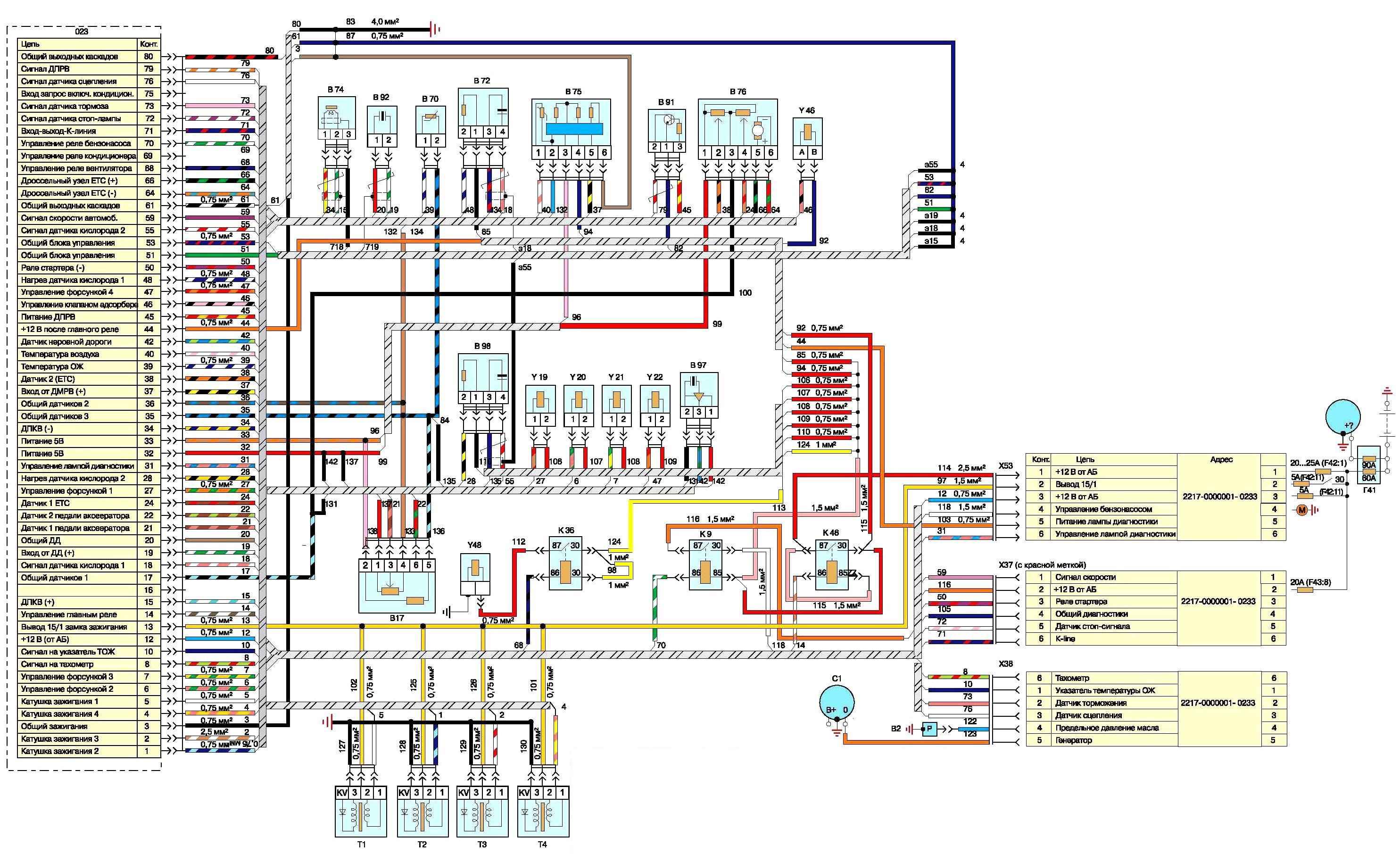
System diagram of the ZMZ-405 engine: A9 - fuel module; B1 - oil pressure indicator sensor; B2 - warning lamp sensor for emergency drop in oil pressure; B5 - warning lamp sensor for emergency drop in brake fluid level; B7 - coolant temperature indicator sensor; B8 - coolant overheat warning lamp sensor; B12 - fuel level indicator sensor; B13 - fuel level indicator sensor in the right tank (GAZ-33027); B17 - accelerator pedal position sensor; B46 - speed sensor; B57 - sensor for turning on the electromagnetic fan clutch; B64, B70 - temperature sensors; B72 - oxygen concentration sensor (for cars with an exhaust gas converter); B74 - synchronization and crankshaft speed sensor; B75 - mass air flow sensor; B76 - throttle position sensor (electronic throttle unit of the ZMZ-40524 engine); B91 - phase sensor; B92 - knock sensor; B97 - rough road sensor; 07 - control unit for the anti-lock brake system (installed on some cars); 021 - heating and ventilation unit control panel; 023 - engine control unit; 027 - instrument dimmer; E1 - left headlight; E2 - right headlight; E9 - left side turn signal; E10 - right side turn signal; E16 - courtesy lamp for the front seats of the cab; E17 - cargo platform lighting lamp (GAZ-3302, -33021, -33027); E18, E19 - lampshades for lighting the cargo compartment of vans; E20 - passenger compartment lighting lamps (right); E27 - left rear lamp; E28 - rear right lamp; E30, E54 - license plate lights; E35 - engine compartment light; E59 - cigarette lighter; E60, E61 - passenger compartment lighting lamps (left); E63 - footrest lamp; E65 - lampshade for lighting the second row of seats (for vans with two rows of seats); E71 - glove compartment lighting lamp; F1-F4 - spark plugs; F41 - additional fuse block; P42 - upper fuse block; P43 - lower fuse block; 01 - generator - battery; H1, H2 - sound signals; H6 - driver signal buzzer (GAZ-3302. -33021, -33027); H62 - left side light lamp; H63 - right side lamp; H70 - rear left fog lamp; H71 - rear right fog lamp; H72 - left reversing lamp; H73 - right reversing lamp; H74 - left brake light lamp; H75 - right brake light lamp; H76 - left side tail light lamp; H77 - right tail light lamp; H78 - left rear turn signal lamp; H79 - right rear turn signal lamp; H98 - left low beam lamp; H99 - right low beam lamp; H100 - left high beam lamp; H101 - right high beam lamp; H102 - left front turn signal lamp; H103 - right front turn signal lamp; K1 - starter relay; K3 - windshield wiper control relay; K7 - signal relay; K9, K46 - relay; K12 - turn signal switch; K13 - breaker for the parking brake warning light; K16 - remote battery switch (for buses - relay for turning on the electromagnetic clutch; K40 - relay for turning on the headlights; M1 - starter; M2 - electric motor for the heater fan; M4 - electric motor for the windshield wiper; M5 - electric motor for the windshield washer pump; M8 - electric pump for the additional heater (for buses and vans with two rows of seats); M10 - electric fuel pump; M20 - electric motor of an additional heater (for buses and vans with two rows of seats); M38 - electric drive for headlight range control (right); M39 - electric drive for headlight range control (left); M43 - heater valve gear motor; P2 - instrument cluster; R12 - resistor of the heater electric motor; P13 - resistor of the additional heater electric motor (for buses and vans with two rows of seats); S1 - switch for the starting system and instruments; S3 - switch for the second lamps row of seats (for RVs with two rows of seats); S5 - alarm switch; S6 - switch for electric motor and electric heater pump; S9 - switch for direction indicators and headlights; S12 - wiper switch; S13 - push-button switch for remote battery switch (for buses); S14 - fuel level sensor switch (GAZ-33027); S29 - reverse light switch; S30 - brake light switch; S31 - switch for the center differential lock warning light (for vehicles with a 4x4 wheel arrangement); S36 - driver signal switch (GAZ-3302, -33021, -33027); S39 - light switch; B52 - switch for the parking brake warning lamp; B54 - switch for checking the serviceability of signal lamps; B60 - glove compartment lamp switch; S62 - switch for the right lamps for lighting the passenger compartment of buses; S63 - switch for the left lamps for lighting the passenger compartment of buses; S73 - switch for the electric motor of the additional heater (for buses and vans with two rows of seats); S116 - headlight range control switch; T1-T4 - ignition coils; U1 – radio receiver; X38, X51 - socket blocks; X53 - pin block; U19-U22 - electromagnetic injectors; U23 - idle speed regulator; U46 - canister purge valve (for vehicles with a fuel vapor recovery system); U48 - electromagnetic clutch for shutting off the engine cooling system fan; (I) - turning on the rear lights of vans and buses; (II) - chassis option; (III) - option with two fuel tanks; I - pin numbers
Checking dead circuits
Before work, we calibrate the ohmmeter. At the selected measurement limit (for most circuits up to 200 Ohms), we close the tips of the probes. On an analog device, use the “0” setting knob to set the arrow to the zero division.
There is no such regulator in household digital devices.
Therefore, before measuring small values (up to 1–2 ohms), by shorting the probes, we determine the internal resistance of the ohmmeter and its wires, which is 0.03–0.06 ohms.
This value must be subtracted from the resulting resistance value.
To check the circuit, we disconnect at least one end of it (otherwise the current will go around, through other sections of the circuit, and the readings will be incorrect).
It is better to put an alligator clip on one of the probes and connect it to ground.
When checking devices with one-way conductivity (for example, a generator rectifier unit), take into account the polarity of the device.
To check the windings of the starter, generator, high-voltage wires, etc. switch the device to the lower measurement limit.
In practice, the accuracy of conventional autotesters is not enough to test sections of the circuit where even the slightest increase in resistance is unacceptable, for example due to poor contact.
Therefore, we pay attention to minor deviations of the needle from the zero division, and after the measurement we check the calibration of the instruments again.
We check the short circuits of the winding to the “housing” and the interturn with a megohmmeter (range “M”).
For many testers (pointer) when operating in this range, an additional DC source is required.
If it is absent, being careful, we check the circuit with a lamp powered by a voltage of 220 V.
Checking live circuits
We check live circuits with a voltmeter and ammeter. We connect the voltmeter in parallel to the device or circuit section being tested. Measurement limit 0–15 or 0–25 V DC.
We connect the negative wire (probe) to ground, the positive wire to consumers or current sources.
By the voltage drop, you can determine a malfunction of the supply circuit (break, oxidation of contacts, etc.), as well as a short circuit in the consumer.
To check live circuits, you can use a test lamp with a power of no more than 3-4 W, designed for a voltage of 12 V (for example, an AMH12-3 lamp used in the instrument cluster).
The ammeter must have an upper measurement limit of 10 A or more direct current, as well as overload protection.
We connect the ammeter in series with the device being tested. We connect the “plus” of the device to the current source, and the “minus” to the consumer.
We measure the current consumption and compare it with the rated one specified in the technical specifications of the device being tested.
Since the actual voltage in the on-board network differs from the rated one (in the reference data the rated current corresponds to the rated voltage, i.e. 12 V), the resulting value may differ slightly from the specified one.
If the current is less than required, then the electrical circuit is faulty, and if it is more, a short circuit has occurred in the consumer.
")

")
")
")
")
")
")
")