Removal and installation of the intermediate shaft ZMZ-406 GAZ-2705
The intermediate shaft drives the oil pump. In addition, camshafts are driven through it
The intermediate shaft rotates in two sleeve bearings.
Withdrawal
Remove the upper and lower camshaft drive chains (article - “Replacing the camshaft drive chains”).
The lower chain does not need to be removed from the crankshaft gear.
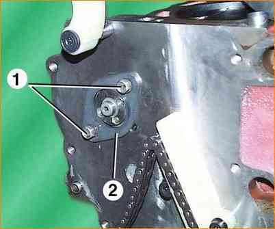
Remove screws 1 and remove intermediate shaft flange 2.
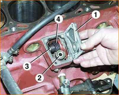
Remove the four bolts securing the cover 1 and remove the cover with the gasket.
Pull up oil pump drive 2 with driven gear.
In order to unscrew the nut 3 and remove the drive gear 4 of the oil pump drive, it is necessary to block the intermediate shaft from turning.
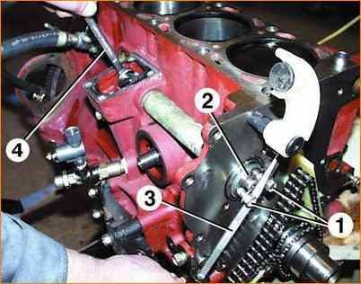
To do this, screw two bolts 1 into the threaded holes of the intermediate shaft 2.
Holding the shaft by the bolts 1 with a screwdriver 3, unscrew the pinion nut with a wrench 4.
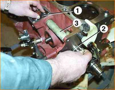
Holding the drive gear 1 with your hand, remove the intermediate shaft 2.
If it is necessary to replace the bushings of the intermediate shaft, you must first press out the pipe 3 of the intermediate shaft using a special tool.
Then, use the special tool to press out the intermediate shaft bushing.
Inspection, Troubleshooting and Repair
After removing, rinse all parts in gasoline.
Inspect the intermediate shaft.
If it has cracks, replace the shaft.
If there are marks, scratches, scuffs, etc. on the shaft journals, grind the shaft journals to the repair size.
If grinding to the repair size fails to completely remove scratches, scuffs, etc., replace the shaft.
Measure the intermediate shaft journals.
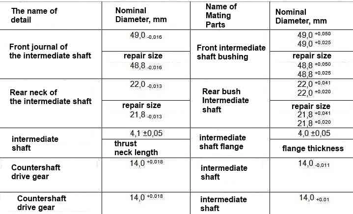
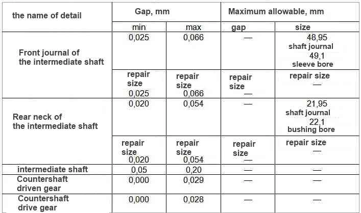
If the diameter of the front neck is less than 48.95 mm, and the rear neck is less than 21.95 mm, they must be ground to the repair size.
The intermediate shaft bushings cannot be repaired.
If they have scuffs, nicks, scratches, etc., they must be replaced.
Increased thickness bushings are available for spare parts.
After pressing new bushings into the cylinder block, they must be bored to the nominal or repair size.
Bore the bushings in one pass to maintain the alignment of the holes.
When pressing the bushings, set them so that the holes in the bushings coincide with the oil channels in the cylinder block.
The dimensions of the journals and bushings of the intermediate shaft are shown in the table.
Nominal and maximum allowable dimensions and fit of the mating parts of the intermediate shaft of the engine mod. 406
Install the shaft in the reverse order of removal. Lubricate the shaft journals and gears with engine oil before installation.


