The causes of malfunction of the master brake cylinder are wear or loss of elasticity of the cuffs, wear of the working surfaces of the cylinder and pistons, swelling of the cuffs from mineral oils entering the system, clogging of the compensation holes
If the fluid level in the master brake cylinder reservoir has decreased, and when inspecting the connections of pipelines and components, including brake mechanisms, no brake fluid leak is detected, then in this case, brake fluid leakage is possible through the outer cuff 8 (see Fig. 1) into cavity A1 of the vacuum booster.
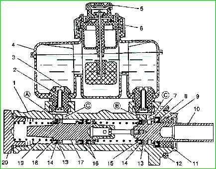
If the brake pedal, when a force of about 200-300 N (20-30 kgf) is applied to it, first moves approximately halfway, and then, under constant force, gradually moves to the cabin floor, then in this case the main cuffs 14 or separating 16.
Defects in the separating cuffs can be detected; to do this, drain the liquid from the tank below the level of the separating partition by 10-15 mm in each section.
If, after pressing the brake pedal 3-5 times, the fluid level in the sections changes, this indicates fluid flow from one section to another, which is only possible when the separating cuffs are worn.
If the cuffs swell, as a rule, the system does not release due to the main cuffs blocking the 14 compensation holes.
To determine this malfunction, simply disconnect the tubes from the master cylinder.
If, after fluid flows out of the working cavities, the leakage stops and the level in the tank does not decrease, then the compensation holes are blocked by cuffs or clogged.
In these cases, the master cylinder should be removed from the vehicle and disassembled.
Removing and disassembling the master cylinder
Removal and disassembly of the main brake cylinder must be performed in the following order:

To prevent dirt from getting into the main brake cylinder, thoroughly clean the connections of the pipes to the main brake cylinder.
Disconnect block 2 with wires from the brake fluid level sensor installed in cover 1 of the master cylinder reservoir and remove the cover.
Unscrew the fastening nuts 3 and disconnect the pipelines from the main cylinder. Plug the pipeline holes.

Unscrew bolt 1 securing bracket 2 of the amplifier to the mudguard.
Unscrew the two nuts 3 securing the brake master cylinder 4 to the vacuum booster, remove the master cylinder with the bracket.
At the same time, make sure that the rubber seal between the cylinder and the vacuum booster does not fall out.
Turn over the master cylinder and drain the brake fluid from the reservoir into a container.
Then press the master cylinder piston several times to remove fluid from it.
- - disconnect the reservoir from the main brake cylinder and remove the connecting rubber bushings 3 with tubes 2 from the cylinder body;
- - unscrew plug 20, remove spring 19 with thrust washer 18. Press piston 10, after which piston 17 with cuffs 14 and 16 can be removed by hand;
- - remove the retaining ring 11 with pliers 7814-5593 or special pliers;
- - remove piston assembly 10 by hand by the shank.
Remove guide sleeve 9, outer collar 8 and thrust ring 7 from the piston.
It is not recommended to unscrew screw 3 unless necessary (Fig. 4) holder.
After disassembly, you must carefully inspect the parts of the master brake cylinder and make sure that the cylinder mirror and the working surfaces of the pistons are completely clean and free of rust, risks and other defects.
If there are defects that cause a significant change in the internal diameter of the cylinder, or if it is worn on one side, replace the body with a new one.
It is recommended to replace the rubber seals with new ones every time the master cylinder is disassembled.
Before assembling the master cylinder, wash all parts in alcohol or clean brake fluid.
Do not allow mineral oils, gasoline, kerosene or diesel fuel to come into contact with the parts, as this may damage the rubber seals.
Assembling the master cylinder
To assemble the brake master cylinder you need:
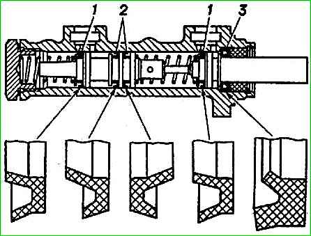
- - install the cuffs on the pistons, as shown in Fig. 5;
- - lubricate the cylinder mirror with brake fluid;

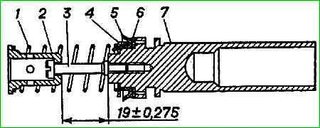
- - assemble the primary piston 6 (see Fig. 6), check the size (19±0.275) mm (not adjustable);
- - lubricate cuff 14 (see Fig. 1) with fresh brake fluid and insert piston 10 into the master cylinder body;
- - insert the thrust ring 7, the outer collar 8, the guide sleeve 9 and the locking ring 11 using tongs or pliers;
- - install separating cuffs 16, piston washer 13, main cuff 14, thrust washer 18 and spring 19 on piston 17;
- - lubricate the cuffs with fresh brake fluid and insert the piston into the cylinder body;
- - overcoming the resistance of spring 19, screw in plug 20 with gasket;
- - install connecting sleeves 3 with tubes 2 into the cylinder body, having previously lubricated them with fresh brake fluid;
- - install tank 4 on connecting sleeves 3;
- - install the main brake cylinder on the vacuum booster, having first checked the condition of the sealing ring 12, and if necessary, replace it;
- - pour brake fluid into the reservoir and bleed the system. Before installing new parts into the main brake cylinder, it is necessary to carefully remove the conservation lubricant from the latter to prevent it from entering the brake system.
")

")
")
")
")
")
")
")