Ignition coils are designed to generate high voltage electric current to ignite the working mixture in the engine cylinders
Ignition coils (2 pcs.) are installed on top of the engine.
The ignition coil structure is shown in Figure 1
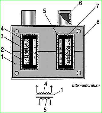
Fig. 1. Ignition coil: 1 - magnetic circuit; 2 - body; 3 - coil; 4 - secondary winding; 5 - primary winding; 6 - high-voltage output; 7 - compound; 8 - fastening bracket
The ignition coil is a transformer.
The primary winding 5 is wound on the magnetic core 1, and the secondary winding 3 is wound on top of it in sections.
The windings are enclosed in a plastic housing 2. The space between the windings is filled with compound 7.
The housing has low and high voltage terminals 6.
Low voltage electrical pulses enter the ignition coil from the control unit.
In the ignition coil they are transformed into high-voltage electrical impulses, which are transmitted through wires to the spark plugs.
Electric discharge occurs simultaneously in two spark plugs of the first and fourth cylinders or the second and third cylinders.
For example, one electrical discharge occurs in the spark plug of the first cylinder when the compression stroke ends there; the second discharge occurs in the spark plug of the fourth cylinder when the exhaust stroke occurs there.
The electric discharge in the spark plug of the fourth cylinder during the exhaust stroke does not affect engine operation.
With further rotation of the crankshaft, an electrical discharge will occur in the fourth spark plug, causing high voltage current leakage and insulation breakdown.
If oil gets on the wires, they should be wiped with a rag soaked in gasoline.
If necessary, check the serviceability of the current-carrying wire with an ohmmeter.
The resistance of the wires to the first and second cylinders should be no more than 1000 Ohms, and the resistance of the wires to the 3rd and 4th cylinders should be no more than 900 Ohms.
Removing the ignition coil
Disconnect the wire from the negative terminal of the battery.

Disconnect the 4 blocks 1 of the low-voltage wires and the high-voltage wires 5 from the coil. Unscrew the bolts 2, remove the bar 3 and the coil 4.
Remove the second coil in the same way.
Checking the ignition coil
Coils 30.3705 and 301.3705 are checked with a spark plug diagnostician 1AP975000 on a car.
To do this, disconnect the high-voltage wires from the coil and connect the diagnostician instead.
Then crank the engine with the starter, and a spark should appear in the diagnostic spark gap in time with the operation of the cylinders.
Check the resistance of the primary winding of the ignition coil by connecting an ohmmeter between the low voltage terminals.
The ohmmeter should show a resistance of 0.4 - 0.5 Ohm.
Then check the resistance of the secondary winding by connecting an ohmmeter between the high voltage terminals of the ignition coil.
The ohmmeter should show a resistance of 5 - 7 kOhm.
If the measured parameters differ from those specified, the coil must be replaced.