Removing the steering mechanism
To do this you need to do the following:
- - remove the cotter pin and unscrew the wedge nut on the steering mechanism, knock out the wedge, eliminating its deformation, and remove the propeller shaft fork from the mechanism shaft;
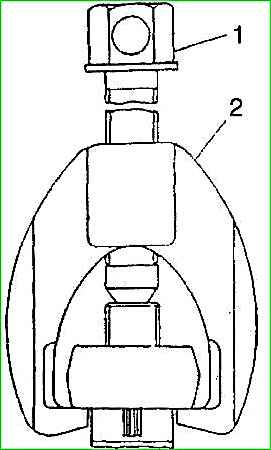
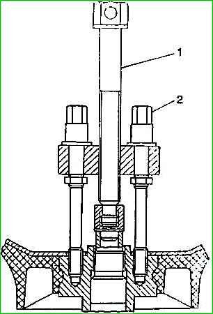
- - unscrew the nut securing the bipod and remove the bipod from the steering gear sector shaft using a puller 7823-6092;
- - unscrew the five nuts securing the steering mechanism bracket to the frame spar and remove the steering mechanism with the bracket; remove the bracket from the steering mechanism.
The removal of the steering mechanism is discussed in detail in the article - Removing the steering mechanism of a Gazelle car
Disassembling the steering mechanism
To disassemble, do the following:
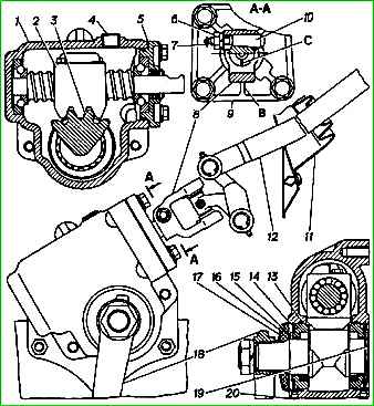
- - drain the oil from the steering housing through filler plug 4
- - clamp the steering mechanism in a vice by the boss under the crankcase mounting hole and thoroughly clean all surfaces of dirt;
- - remove two plugs from the crankcase;
- - remove covers 17, 19 and sponge seal 16 from the sector shaft;
- - straighten the holes on the bearings 15 of the sector shaft with a beard;
- - remove the bearings 15 of the sector shaft with a puller one by one without impacts or distortions, preventing the rollers from scattering.
Rearranging bearings to the other end of the shaft or mixing the rollers of one bearing with the rollers of another bearing is unacceptable.
- - remove sector shaft 3 and sealing rings 13;
- - unscrew the bolts securing the upper crankcase cover and remove the upper cover together with the gaskets;
- - press the oil seal and bearing race out of the top cover, having first removed the sealing ring and gaskets 5;
- - remove screw 2 assembled with nut;
- - press out the remaining outer race of the propeller bearings.
Do not press out the outer races of the propeller bearing from the crankcase and the top cover unless necessary.
Inspection of steering gear parts
Parts of the disassembled steering mechanism should be washed in kerosene or other liquid that makes it easier to remove grease, dirt and metal wear particles from the parts.
Before assembling the steering mechanism, you should inspect all its parts to determine the need to replace worn parts.
Steering gear housing:
If cracks and breaks are detected, the crankcase must be replaced.
Screw with steering gear nut:
If dents appear on the surface of the screw or if it jams when turning the screw in the nut, it should be replaced as an assembly with the nut.
Shaft sector:
If there are cracks and dents on the working surfaces of the shaft, the sector shaft must be replaced.
Bearings:
The bearings must be washed in clean kerosene and blown with compressed air.
If the bearings have cracks, wear on the raceways and balls, or cracks in the cage, then such bearings must be replaced.
Rubber sealing rings
If the O-rings have lost their original shape or have tears or cuts, the rings must be replaced.
Assembling the steering mechanism
To assemble, you need to do the following:
- - lubricate the working surfaces of the steering mechanism parts with a thin layer of lubricant;
- - press the propeller bearing race all the way into the steering gear housing and install the O-rings;
- - press the screw bearing race, oil seal into the top cover and install the o-ring;
- - check the quality of pressing of the bearing races with a feeler gauge;
- - install the screw with nut and bearings into the crankcase;
- - install and bolt the upper cover of the steering mechanism, adjusting the tightening of the screw bearings.
The top cover bolts must be tightened to a torque of 24–36 Nm (2.4–3.6 kg/m);
- - install the sector shaft into the crankcase, and the middle tooth of the nut should fall into the middle cavity of the sector shaft;
- - install the assembled bearings;
- - adjust the grip alignment of the sector shaft with a nut;
- - perform subassembly in the reverse order of disassembly;
- - install the steering mechanism on the car.
The bolts securing the bracket to the steering mechanism must be tightened to a torque of 44-62 Nm (4.4-6.2 kg/m), the nuts securing the bracket to the spar - to a torque of 28-36 Nm (2.8-3.6 kg /m);
- install the propeller shaft fork onto the steering gear shaft, drive the wedge into the fork and tighten it with a nut to a torque of 1 8-25 Nm (1 8-2.5 kg/cm).
Install flat and spring washers under the nut on the side of the machined surface on the fork, secure the wedge with cotter pins;
- install the bipod on the steering gear sector shaft and secure it with a nut, tightening torque 105-140 Nm (10.5-14 kg/m).
Removing the steering wheel driveshaft
To remove the cardan shaft you must:
- - remove the two cotter pins of the hinges, unscrew the nuts securing the wedges, knock out the wedges, remove the pistons and remove the propeller shaft with the seal;
- - remove the cotter pin on the propeller shaft joint, unscrew the wedge nut, knock out the wedge and remove the propeller shaft joint.
Disassembling the steering column driveshaft
During the disassembly process it is necessary:
- - clean the propeller shaft joint from dirt and oil;
- - remove the retaining rings of the crosspiece bearings;
- - press out the crosspiece bearings on a press or in a vice using a bronze reference, the outer diameter of which is slightly smaller than the hole in the fork.
To do this, install the mandrel on the bottom of the needle bearing housing and press out the opposite bearing.
Turn and press out the other bearing, installing the reference into the end of the crosspiece tenon;
- - turn the shaft ¼ turn and press the bearings out of the ears of the second fork in the same sequence;
- - remove the cross. Wash all parts of the universal joint in kerosene and check their condition. Replace worn parts.
The propeller shaft joint mounted on the steering gear shaft is disassembled in a similar way.
Assembling the steering column driveshaft
To assemble, you need to do the following:
- - lubricate the bearings and crosspiece with a thin layer of grease, insert the spikes of the crosspiece into the eye of one of the forks so that the oiler does not cover the cheek of the fork;
- - using a mandrel, press first one bearing into the cardan fork, and then the second;
- - install retaining rings;
- - turn the driveshaft 1/4 turn and, in the same sequence, press in and secure with retaining rings the other two bearings in the ears of the second crosspiece;
- - lubricate the crosspiece bearings through a grease nipple;
- - after installing the wedge, install the washers and nut on the machined surface of the fork. Seal the wedges;
- - tighten the wedge nuts to a torque of 12-18 Nm (1.2-1.8 kg/m).
Assembly of the propeller shaft joint mounted on the steering gear shaft is carried out in a similar way.
Removing the steering wheel
To remove the steering wheel you must:
- - remove the steering gear lining;
- - unscrew the steering wheel nut, remove the lock washer;
- - make a mark on the steering wheel hub and on the end of the shaft to determine their relative position;
- - remove the steering wheel using a puller.
Installing the steering wheel
To install the steering wheel you need:
- - install the steering wheel according to the previously marked marks on the steering wheel hub and on the end of the shaft;
- - install the lock washer and secure the steering wheel. The tightening torque of the nut should be 65–80 Nm (6.5–8.0 kg/m);
- - install the pad on the steering wheel.