Cooling system ZMZ-40524 - liquid, closed, with forced circulation of coolant.
The engine cooling system consists of cooling jackets for cylinder block 6 and cylinder head 1, water pump 5 with an electromagnetic clutch, thermostat 2, drain plug 7, control system coolant temperature sensor 3.
The circulation of coolant in the system is created by a centrifugal water pump driven from the crankshaft.
The pump supplies liquid to the cooling jacket 6 of the cylinder block, from where the liquid enters the jacket 1 of the cylinder head and then to the thermostat housing 2.
Thermostat 2 automatically regulates the supply of coolant to the radiator depending on its temperature.
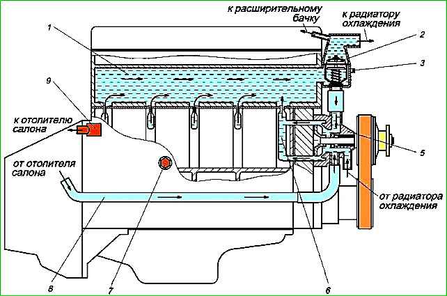
Through the fitting of the thermostat cover, air and steam generated in the cooling system are vented into the expansion tank when the system is filled.
The coolant is drained from the engine through the hole on the left side of the cylinder block, closed with plug 7.
The optimal temperature regime of the coolant from the point of view of minimum wear and fuel consumption is within the range of 80-90°C.
The engine temperature control is carried out using a temperature indicator and an overheating indicator (control lamp), located in the vehicle instrument cluster.
The coolant temperature indicator is controlled by a signal generated by the control unit based on information from temperature sensor 3 located in the thermostat housing.
In the vehicle's instrument cluster, information about the current engine temperature is read from the coolant temperature indicator, and if the maximum permissible value of 105°C is exceeded, the coolant overheat warning lamp lights up.
The indicator color is red.
Thermostat
The thermostat is a solid-filled, two-valve type with an automatic drain valve, model TS 107-05, TR 2-01 or TA 107-05.
The thermostat is located in an aluminum housing installed at the outlet of the cylinder head cooling jacket, and is connected by hoses to the water pump, radiator and expansion tank.
The thermostat automatically maintains the required temperature of the coolant in the engine, turning off and turning on the circulation of fluid in a large circle through the radiator.
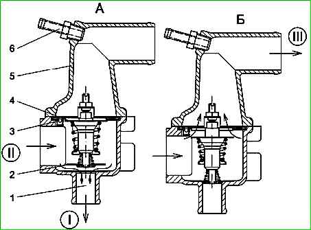
On a cold engine, the main thermostat valve 4 is closed, and all the coolant circulates through the open thermostat bypass valve 2 to the water pump in a small circle, bypassing the radiator.
When the engine warms up and the coolant temperature rises to 82 ± 2°C, the main thermostat valve begins to open and the bypass valve begins to close.
At the same time, part of the coolant begins to circulate in a large circle through the cooling radiator.
At a temperature of 97 ± 2°C, the main valve is fully open by at least 8.5 mm, the bypass valve is closed and all the coolant circulates through the radiator in a large circle.
There is a hole in the thermostat flange with an automatic drain valve 3.
The hole is used to allow air to escape when filling the cooling system.
When the engine is running, the water pump creates fluid pressure, under the influence of which the valve ball rises and closes the hole, preventing fluid from leaking into the radiator.
The tightness of the connection between the thermostat cover and the housing is ensured thanks to a U-shaped rubber gasket installed on the thermostat flange.
The thermostat must be installed in the housing in such a way that the protrusion on the thermostat stand fits into the groove of the housing, which provides the least resistance to the flow of coolant.
It is prohibited to operate the engine without a thermostat, which will lead to overheating of the engine in the summer, and in winter - to long warm-up and operation of the engine at a reduced temperature mode.
Maintaining the operating temperature in the cooling system by the thermostat has a decisive influence on the wear of engine parts and the efficiency of its operation.
Possible malfunctions of the cooling system and ways to eliminate them
Cause of malfunction - Remedy
Engine overheating:
- The radiator core is clogged with dirt and insects - Wash the outside of the radiator core. Blow with compressed air.
- Reduced coolant level in the expansion tank - Find the location of the coolant leak. Fix the leak. Add coolant.
- The thermostat is faulty (the valve is stuck in the closed position) - Replace the thermostat.
- Water pump is faulty - Check the pump, replace if faulty.
- Damage to the valve in the expansion tank plug (the valve is constantly open, causing the system to be under atmospheric pressure) - Replace the expansion tank plug.
- Radiator tubes, hoses and engine cooling jacket are clogged with scale and silt deposits - Flush the cooling system and fill with fresh coolant.
Engine overheating, cold air coming from the heater:
- Excessive reduction in coolant level due to a leak or damage to the cylinder head gasket, causing vapor locking in the engine water jacket - Repair the coolant leak. Replace damaged cylinder head gasket.
Engine does not warm up to operating temperature for a long time:
- The thermostat is faulty (the valve is stuck in the open position) - Replace the thermostat.
Constantly decreasing coolant level in the expansion tank:
- Radiator leaking - Replace radiator.
- Expansion tank leaking - Replace expansion tank.
- Coolant leaks through leaky connections of pipes and hoses - Tighten the hose clamps.
- Water pump seal damaged - Replace water pump.
- The sealing gasket of the water pump housing is damaged - Replace the sealing gasket.
- The cylinder head mounting bolts are not tightened sufficiently (during long-term parking on a cold engine, a coolant leak appears at the junction between the cylinder head and the cylinder block) - Tighten the cylinder head mounting bolts to the required torque.
The design of the coolant pump is discussed in the article - Design features and replacement of the water pump of the ZMZ-40524 engine
")

")
")
")
")
")
")
")