The direction the vehicle is turning is indicated by flashing lights in the front and rear turn signals
The turn indicators are turned on by a switch located under the steering wheel
When you move the lever up, the right turn indicators turn on, and when you move the lever down, the left turn indicators turn on.
Moving the lever toward or away from you switches the headlights.
Moving the lever towards you to a non-fixed position briefly turns on the headlights (for signaling).
When the handle is moved along the axis of the lever, a sound signal is activated.
On some vehicles, the sound signal is turned on by the windshield wiper and washer switch.
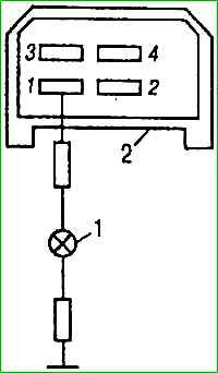
The switch consists of a mechanical drive that provides manual activation and a switch designed to connect the electrical circuits of signal lamps with a current source.
When the spiral of one of the signal lamps burns out, the frequency of flashing of the signal lamp doubles.
Poor clarity of switching on and lack of light in the direction indicators can occur as a result of burning of the switch contacts, as well as due to malfunctions of the lamps and their sockets.
To troubleshoot, first make sure that the lamps and their sockets are in good condition.
Change lamps only when the turn signal switch is off and the hazard warning switch is off.
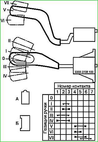
Check the correct operation of switches 3302.3709100 and 1102.3769 using a test lamp according to the connection diagrams respectively shown in Fig. 1 and 2.
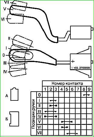
The force of moving the lever should be in the range of 5-25 N (0.5-2.5 kgf).
The voltage drop across the terminals should be no more than 0.3 V at a current of 5 A. If the switch does not operate correctly, replace it.
Turn signal and hazard warning switch 494.3747
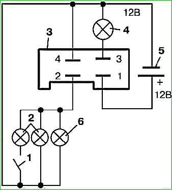
To create an intermittent operation of the direction indicators, a turn indicator and hazard warning switch 494.3747 is used.
The interrupter ensures intermittent operation of signal lamps with a frequency of (90±30) cycles per minute.
The breaker has the function of monitoring the serviceability of signal lamps.
If one of the warning lamps burns out or there is no contact when the turn indicators are turned on, the breaker ensures intermittent operation of the warning lamp with a frequency of 240±(30) cycles per minute.
The breaker is a non-repairable product. The serviceability of the breaker should be checked according to the diagram in Fig. 4.
If the warning lights do not light up, light up constantly or not at the specified frequency, they must be replaced.
Switch for direction indicators, headlights and horn*
The direction the vehicle is turning is indicated by flashing lights in the front and rear direction indicators.
The turn indicators are turned on by a switch located under the steering wheel.
Moving the lever towards you to a non-fixed position briefly turns on the headlights (for signaling).
When the handle is moved along the axis of the lever, a sound signal* is activated. * On some vehicles, the horn is activated by the windshield wiper and washer switch.