Removal and repair of GAZ-2705 shock absorbers
Shock absorbers are designed to dampen vehicle vibrations that occur when driving on uneven roads
Their action is based on the use of resistance to fluid flow through small flow sections in compression and return valves.
The comfort of the car and the durability of body and chassis parts largely depend on the performance of shock absorbers.
Normal working shock absorbers should dampen vehicle vibrations after moving over an obstacle in 1-3 strokes.
If you experience squeaks or knocks when driving off-road, you need to check the condition of the shock absorbers.
Inspect the shock absorber rod.
If the rod is bent or there are peelings of the chrome coating on the working surface, traces of corrosion, scuffing, damage to the threaded part or key flats, then the shock absorber must be replaced.
Removing and installing the shock absorber
Jack up and remove the front wheel of the car. If we are working on an inspection ditch, we don’t have to do this.

Use a 19mm socket to unscrew the nut of the shock absorber lower mounting bolt.

Remove the outer washer.

We do the same with the upper shock absorber mount

Remove the shock absorber

Remove the internal washers

Remove the rubber bushings from the shock absorber eye
We install a new shock absorber with new rubber bushings in the reverse order. Similarly, we replace the shock absorber on the other side of the car.
The rear suspension shock absorber is removed in the same way.
Shock absorber repair
The shock absorber should be disassembled only in case of obvious shock absorber malfunctions.
The extent of disassembly depends on the nature of the malfunction. So, if tightening the reservoir nut does not prevent fluid leakage, then the shock absorber must be partially disassembled.
Disassemble shock absorbers in the following order:
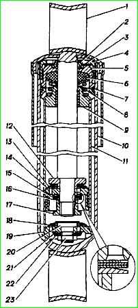
- - clamp the lower eye in a vice, pull rod 1 (see Fig. 1) past the stop and unscrew nut 4 of the tank;
- - carefully swing the race 5 of the oil seal 6 by the rod 1 and lift the cylinder 11 from the reservoir;
- - holding the cylinder with one hand and without removing it from the tank, use a copper hammer to knock out guide 9 of the rod from the cylinder;
- - lower the cylinder to the bottom of the tank and, holding it, remove the rod with piston 14; drain the liquid from the reservoir and cylinder into a measuring cup;
- - remove the cylinder from the tank and, holding the lower part of the compression valve body 19 in a vice, swing the cylinder and release it from the valve body.
As a rule, the compression valve is not disassembled, but only thoroughly washed with kerosene m and is pressed into the cylinder in its original place.
If it is necessary to disassemble it, unscrew nut 23;
- - hold the rod by the upper eye in a vice and unscrew the nut 17 of the recoil valve, remove in sequence the restrictor plate 16, discs 15, piston 14, plate 13, spring and restrictor plate 12. The remaining part of the liquid goes into the reservoir.
Remove the cylinder from the reservoir and, supporting the cylinder above the reservoir, check the flow of fluid through the compression valve.
If assembled correctly, there should be a drip of liquid;
- - insert the rod with piston 14 into the cylinder without distortion, install the rod guide 9 into the cylinder and slowly, so that there is no splash of liquid, lower the cylinder into the reservoir;
- - tighten nut 4 with a torque of 70-90 Nm (7-9 kgcm) with the rod extended.
When the nut is tightened, the guide rod is pressed into the cylinder.
After assembling the shock absorber, you should push the rod in and out several times until a uniform force appears along the entire length of its stroke.
To check the tightness of the shock absorber, it is recommended that after assembly, keep it in a horizontal position with the rod pushed all the way in for at least 10 hours.
Shock absorber malfunctions and solutions
- Cause of malfunction
Remedy
Fluid leakage from shock absorber:
- Loosening the reservoir nut
Tighten the nut
- Rod seal wear
Replace the oil seal
- Nicks or marks on the rod, wear of the rod until the chrome layer comes off
Replace the rod
The absence of a chrome layer is checked by the redness of the rod when wetting it with a solution of copper sulfate
Unsatisfactory performance of the shock absorber (frequent breakdowns, car rocking):
- Insufficient amount of fluid in the shock absorber
Remove the shock absorber from the car, disassemble it, replace faulty parts and add fluid
Insufficient force during the recoil stroke (when stretching the shock absorber):
- Piston bushing wear
Replace the bushing
- Nadirs on the piston or cylinder
Replace damaged parts
- Leaky overlap of the bypass valve
Disassemble and wash the shock absorber. If necessary, replace the valve and its parts
Insufficient force (or “failures”) during the compression stroke:
- Loose closure of the compression valve due to foreign particles
Wash the shock absorber parts, fill with fresh fluid
Knocks and squeaks when the shock absorber operates:
- Looseness or wear of the bushings of the upper and lower shock absorber lugs
Tighten loose nuts. Replace damaged bushings
- Excessive amount of fluid in shock absorber
Pour liquid into the shock absorber in a strictly defined amount
- Self-loosening the recoil valve mounting nut
Tighten the nut
")

")
")
")
")
")
")
")