On cars with a ZMZ-406 engine, a starter 42.3708-10 is installed on the clutch housing on the right side, and with a ZMZ-402 engine - ST230-B4 - on the left side of the clutch housing
Both starters are similar in design and are a DC electric motor with electromagnetic excitation.
The starter has four poles.
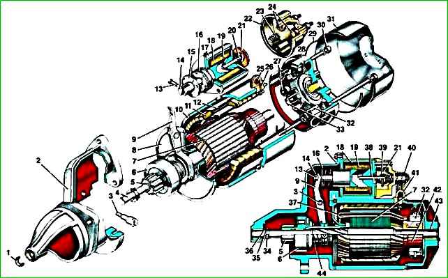
Starter: 1 - plug; 2 - drive side cover; 3 - lever axis; 4 - armature shaft; 5 - drive gear; 6 - starter drive; 7 - anchor; 8 - intermediate support; 9 - drive lever; 10 - body; 11 - stator winding; 12 - pole; 13 - rivet; 14 - traction relay anchor; 15 - spring support washer; 16 - relay armature spring; 17 - traction relay housing; 18 - holding winding; 19 - retractor winding; 20 - spring; 21 - contact disk; 22 - traction relay cover; 23 - spring; 24 - contact bolt; 25 - output; 26 - insulating sleeve; 27 - brush spring; 28 - cover from the collector side; 29 - sealing ring; 30 - coupling bolt; 31 - protective casing; 32 - brush; 33 - brush holder; 34 - thrust ring; 35 - retaining ring; 36 - thrust washer; 37 - rotor winding; 38 - relay armature plunger; 39 - insulating sleeve; 40 - contact bolt of traction relay; 41 - protective cap; 42 - collector; 43 - rotor shaft bushing; 44 - buffer spring
A traction relay is installed on top of the starter housing, which has two windings: retracting and holding.
When the key in the ignition switch is turned to position “II”, the power circuit of the traction relay windings is turned on, while the relay armature is retracted and through the lever engages the starter gear with the engine flywheel ring gear.
At the end of the stroke, the armature turns on the starter power circuit and simultaneously turns off the relay winding (power is supplied only to the holding winding).
When the key in the ignition switch is returned to position “I,” the power supply circuit of the starter and the retaining winding is turned off, and under the action of the spring, the armature disengages the starter gear from the flywheel ring gear.
The design of the ST230-B4 starter is shown in the figure, and disassembly is shown using the example of starter 42.3708-10.
Removing the starter
Disconnect the wire from the negative terminal of the battery.

Disconnect the wires from the two terminals of the starter traction relay.

Unscrew the two nuts of the upper and lower fastenings and remove the starter.
On the ZMZ-402 engine, first unscrew the guide tube of the oil level indicator (dipstick)
Disassembling the starter
Clean the starter from dirt.

Unscrew two screws 1 and remove cover 2.
Unscrew nut 4 and disconnect bus 3 from the traction relay terminal.

Remove retaining ring 1.
Unscrew the two fastening nuts 2 and remove the cover 3 from the manifold side.

Unscrew the two fastening screws 1 and remove the traction relay 2. In this case, the armature should remain on the drive lever.

Use a screwdriver to remove the rubber seal of lever 1. Remove armature 2 of the traction relay; to do this, press armature 2 down and disconnect it from the lever.

Remove stator 1 with brush holder 2.
To disconnect the brush holder from the stator, it is necessary to press the ends of the springs 3 and remove two insulated brushes 4 from the holders (these brushes remain on the terminals of the stator winding).

Unscrew the lever axis, having first unscrewed the lock nut on the other side.

Remove cover 1 from the drive side and remove lever 2.

Knock retaining ring 1 through the mandrel in the direction of the arrow and remove the retaining ring installed under the retaining ring.
Remove the starter drive 2 assembly from the armature shaft.
Checking and inspection of starter parts
Clean all starter parts.

Check the condition of the stator winding.
To do this, turn on the test lamp in the 220 V AC circuit and connect it to one of the terminals of the stator winding, the other end of the circuit must be closed to the stator housing.
The lamp should not be lit.
If the lamp is on, it means the winding insulation is damaged. In this case, replace the winding or stator.
Check the second winding in the same way.
Inspect the anchor.
If the collector is dirty or has marks, scratches, etc., sand the collector with fine glass sandpaper.
If the commutator is significantly rough or mica protrudes between its plates, grind the commutator on a lathe and then grind it with fine glass sandpaper.
The commutator runout relative to the shaft journals should not exceed 0.05 mm.
If yellow deposits from the bearing are found on the armature shaft, remove it with fine sandpaper, as this can lead to the gear sticking on the shaft.
Check the reliability of soldering of the armature winding leads to the collector plates.
Inspect the winding at the ends of the armature; the diameter of the winding should be less than the armature iron package. Otherwise, replace the anchor.

Check the condition of the armature winding using the E-236 device or a test lamp powered by 220 V alternating current.
Voltage is supplied to the commutator plate and the armature core.
The lamp should not be lit. If the lamp is on, it means there is a short circuit in the armature winding or commutator plate to ground. In this case, replace the anchor.
Place the starter drive onto the armature shaft; it should move freely, without jamming, along the splines of the armature shaft.
Holding the anchor, turn the starter gear in both directions: the gear should rotate freely clockwise, but should not rotate counterclockwise. Otherwise, replace the drive.
Traction relay
Check the resistance of the traction relay windings with an ohmmeter.

The resistance of the pull-in winding should be in the range of 0.300–0.345 Ohms, and the holding winding – 1.03–1.11 Ohms.
The windings can also be checked by connecting the battery to the terminals of the windings.
To check the pull-in winding, you need to disconnect the terminal from contact bolt 1 of the traction relay.
Then connect the “–” of the battery to terminal 2, and the “+” to terminal bolt 1 (red diagram). In this case, the relay armature should be sharply retracted.
To check the holding winding (with terminal 1 disconnected from the contact bolt), connect the “+” battery to terminal 2, and the “–” to the starter housing.
In this case, the armature of the traction relay should smoothly retract. Otherwise, replace the traction relay.
The traction relay armature must move freely in the housing, without jamming. Inspect the contact bolts.
Clean the burnt bolt heads with fine sandpaper.
If the bolt heads are severely burnt, you can rotate the bolts 180° so that they are pressed against the contact disk with the unburnt side.
If the surface of the contact disk is heavily worn, it can be turned with the unworn side towards the contact bolts.
Check the movement of brushes 1 in holders 2 and 3; the brushes should move easily, without jamming.
Check that brush holders 2 and 3 are securely fastened; the holders should not be loose.
The holders of the 3 insulated brushes must not have a short to ground (check using indicator lamp).
Check the force of the springs 4 pressing the brushes using a dynamometer.
To do this, you need to install the brush holder 5 into the cover on the commutator side, insert the armature, and install the brushes on the commutator.
At the moment the spring comes off the brush, the force should be in the range of 8.5–14 N (0.85–1.4 kgf). The ends of the springs should press on the middle of the brush.
Brushes worn to a height of 5.0 mm must be replaced (brush leads are soldered).
Inspect the starter covers and replace them if cracks are found.
If the bushings 1 in the covers on which the armature shaft rotates are worn out or have burrs, holes, etc., it is necessary to replace the covers with defective bushings.
Assembling the starter
Assembling the starter is carried out in the reverse order of removal.
When assembling, lubricate the bearings (bushings), splined part and shaft journals with engine oil.

After assembly, check dimension “A”, it should be no more than 34 mm.
Turn on the traction relay and measure dimension “B” between the end of the gear and the thrust ring, it should be within 3–5 mm.
If dimension “B” does not fall within this limit, then adjust its position by turning the lever axis.
To do this, loosen the locknut, turn the axle and tighten the locknut.
After final assembly, it is recommended to check the starter at a service station on a mod stand. 532M.
The ST230-B4 starter is considered serviceable if, at a voltage of 12 V, it consumes a current of no more than 85 A and develops a rotation speed of at least 4000 min –1.
Starter 42.3708–10 at a voltage of 12 V should have the following parameters: 75 A and 5000 min –1.
")

")
")
")
")
")
")
")