The front axle is removed from the car in the following sequence:
- - loosen the wheel nuts
Raise the front part of the car until the wheels are off the floor and install supports under the front part;
- - remove the front wheels;
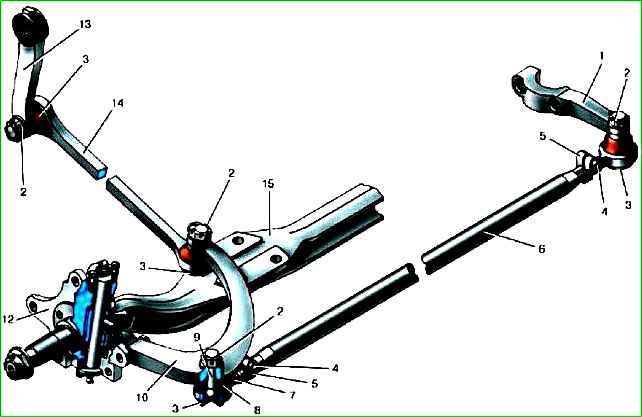
- - unscrew the nut securing the ball pin of the longitudinal link to the bipod of the steering mechanism and disconnect the link;
- - disconnect the lower ends of the shock absorbers from the front axle beam.
Place a jack under the beam, unscrew the nuts of the spring ladders and remove the front axle from the car.
The beam is installed in the reverse order.
Replacing the kingpin and bushings
Pin 11 and bushing are replaced when their total wear reaches 0.5 mm.
The kingpin and bushings can be replaced without removing the front axle from the car, in the following sequence:
- - lift the car by the front beam so that the wheels do not touch the floor, place it on stands and remove the front wheels;
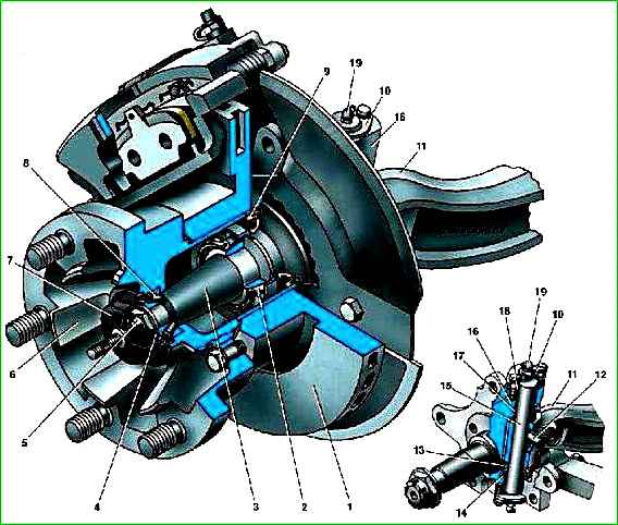
- - remove the brake caliper and place it on the frame; remove hub 6 assembled with disk 1 and bearings;
- - unscrew the bolts and remove the upper and lower king pin covers;
- - unscrew the nut, remove the washer and knock out the locking wedge 12 with a punch;
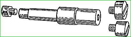
- - using a special drift ( ) with replaceable heads, knock the king pin down from the steering knuckle;
- - remove the steering knuckle and thrust bearing;
- - hold the steering knuckle in a vice and use a mandrel to knock out the pin bushings;
- - clean the holes for the kingpin in the steering knuckle;
- - use a mandrel to install new bushings;
- - unfold the bushings into the passage using a special reamer up to x25 mm;
- - clean the bushings from metal shavings and apply a thin layer of lubricant to each bushing;
- - install the steering knuckle on the front suspension beam;
- - insert a new king pin into the upper knuckle boss, install a thrust bearing with a protective cap and push the king pin until the flat coincides with the hole in the beam.
Before installation, lubricate the surface of the pin with a thin layer of lubricant;
- - perform all subsequent assembly operations in the reverse order of disassembly;
- - after assembly, lubricate the steering knuckle pin through the grease nipples and check the wheel alignment.
Replacing the kingpin thrust bearing
The thrust bearing is replaced if its height wear has reached more than 1 mm.
If the gap is less than 1 mm, a steel spacer of appropriate thickness is installed between the upper knuckle boss and the beam boss.
To replace the thrust bearing and install the shim, you must first perform the operations in the sequence specified for replacing the kingpin
After the kingpin is knocked out of the thrust bearing area, remove the worn one, put a new bearing in place, lift the steering knuckle until the bearing is tightly pressed to the beam, and use a feeler gauge to measure the gap between the upper knuckle boss and the beam boss.
If the latter exceeds 0.15 mm, install an adjusting shim in the gap, then assemble the axle in the reverse order of disassembly.
Replacing the steering rod joint
Replacement of the steering rod joint must be done in the following order:
- - unscrew and unscrew the steering wheel fastening nuts gi to the bipod of the steering mechanism and to the steering knuckle;
- - press the fingers out of the conical holes using a universal puller or knock them out with a hammer through the copper gasket;
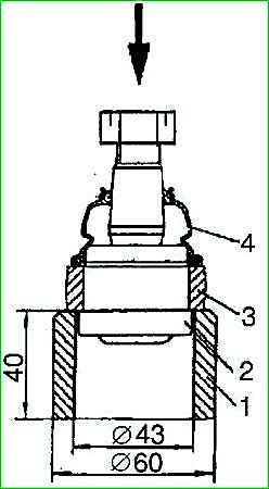
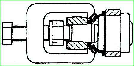
- - on a press, using support sleeve 1, press the hinge out of the rod, applying force to the pin with the nut pre-screwed to the level of the end. At the same time, the protective cap 4 is pressed off the hinge body;
- - clean the surface of the socket under the hinge in the longitudinal link;
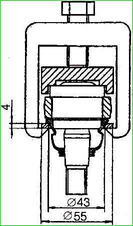
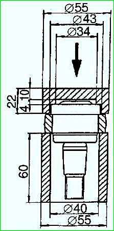
- - press the new hinge into the longitudinal link using a support sleeve and a pressure heel
- - take a new protective cap and put it on the body and hinge pin using a universal puller and washer, after putting 1 to 1.5 g of lubricant into it;
- - secure the cap on the finger with a locking ring. When assembling the hinge, avoid mechanical damage to the rubber cap;
- - install the linkage on the car in the reverse order of disassembly.
Replacing the tie rod joint
Replace the tie rod joint in this order:
- - undo the cotter pin and unscrew the nut securing the hinge to the steering linkage arm;
- - press the pin out of the conical hole of the lever using a universal puller or knock it out with a hammer through the copper gasket;
- - unscrew the tie rod clamp bolt;
- - roll the tip off the threaded end of the rod.
Next, the hinge is replaced in the sequence indicated for the longitudinal link.
")

")
")
")
")
")
")
")