The intake system consists of an intake pipe and a receiver cast from aluminum alloy.
The geometric parameters of the system make it possible to implement gas-dynamic supercharging of the engine - improving the filling of the engine cylinders at a certain operating mode.
The receiver has additional fastenings to the cylinder head to increase rigidity and reduce vibration.
To regulate the air supply to the engine, a throttle module with an electric throttle drive and a throttle position sensor, controlled from the control unit, is used.
The throttle position is determined by the current engine operating mode and the position of the gas pedal.
At idle, air is supplied to the engine cylinders as in all other modes - through the throttle, receiver and intake pipe.
Because of this, there is no idle air duct in the intake pipe.
The exhaust manifold is cast from high-strength cast iron.
To improve the cleaning of engine cylinders from exhaust gases, the pipes from cylinders 1 and 4, 2 and 3 are connected to each other.
This reduces the influence of the operation of one cylinder on another and allows the effect of tuned exhaust to be realized.
The flanges of the manifold connecting to the cylinder head are interconnected by ribs, which increases the rigidity of the structure.
The exhaust manifold is attached to the cylinder head through a two-layer steel gasket, ensuring high reliability of the connection.
The manifold is covered with a stamped steel screen to reduce the thermal effect on surrounding parts of the vehicle's engine compartment.
Crankcase ventilation system
The crankcase ventilation system is closed, forced, operating due to the vacuum in the intake system created during engine operation.
The system is equipped with a pressure reducing valve (vacuum valve) that maintains a constant vacuum in the engine crankcase.
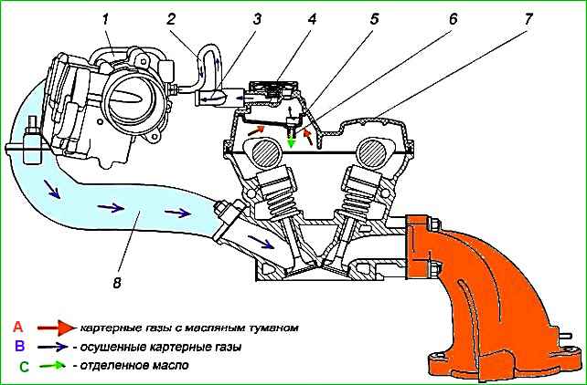
The valve cover pipe is connected to the air intake system.
Under the influence of vacuum in the intake system, gases that break through during fuel combustion into the engine crankcase enter with oil mist into the cylinder head and then into the cavity formed by the valve cover and oil deflector 5.
Passing through the labyrinth formed by the partitions of the oil deflector and the valve cover, oil vapors are separated from the crankcase gases, and the dried crankcase gases enter through the vacuum valve 4 into the air intake system and into the engine cylinders, where they are burned.
The oil separated in the oil separator accumulates in the grooves of the oil deflector, from where it drains through the holes in tubes 6 into the cylinder head.
The suction of crankcase gases from the valve cover when the engine is running at idle and partial loads is carried out through the small ventilation branch 2 into the receiver 1, in other modes - through the main crankcase ventilation branch 3 into the intake system in the area between the air filter and the throttle.
Attention!
It is prohibited to operate the engine with a leaky ventilation system and an open oil filler pipe. This will cause increased oil carryover with crankcase gases and environmental pollution.
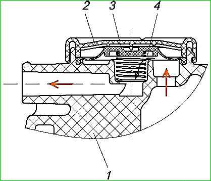
The vacuum valve serves to maintain the vacuum in the engine crankcase at a constant level in all operating modes and thereby increases the reliability of the crankshaft oil seals. The vacuum valve is installed in the valve cover.
Thanks to the vacuum valve, a vacuum of 40 - 50 mm H₂O (400 - 500 Pa) is constantly maintained in the engine crankcase.
The valve consists of a rubber diaphragm 3 and a spring 4, closed by a cover 2. Depending on the vacuum in the intake system, the diaphragm 3, overcoming the force of the spring 4, changes its position and thereby increases or decreases the cross-section of the air channel connecting the valve cover with the intake system.
If there is a strong vacuum in the intake system (for example, with an excessively dirty air filter), the valve diaphragm completely blocks the crankcase gas suction channel.
Maintenance of the crankcase ventilation system
Maintaining the crankcase ventilation system involves periodically washing and cleaning the channels and hoses.
The operation of the crankcase ventilation system can be checked as follows:
When the engine is running at minimum crankshaft speed in idle mode, there should be a vacuum in the engine crankcase, but not more than 50 mm H₂O (500 Pa).
This is determined using a water piezometer connected to the engine crankcase through the oil level indicator tube.
Crankcase gas pressure is possible due to coking of the ventilation system channels or sticking of the vacuum valve diaphragm and complete blocking of the crankcase gas suction channel, or increased gas blow-by into the engine crankcase.
When the vacuum in the engine crankcase is more than 50 mm H₂O (500 Pa), check the condition of the vacuum valve parts. Replace the damaged diaphragm.
With increased oil consumption due to waste, pay attention to the tightness of the oil deflector and clogging of the holes in the oil drain tubes of the oil deflector.
Leakage of the oil deflector or its installation will lead to the passage of part of the crankcase gases with oil mist past the labyrinth of the oil separator, incomplete separation of the oil, its suction with the crankcase gases into the engine cylinders and waste.
The defect should be eliminated by installing the oil deflector on sealant or by replacing it.
Every 40,000 km or if crankcase gas pressure is present, parts of the ventilation system should be cleaned:
- Remove the ventilation hoses with the ventilation tube and the valve cover. Remove the oil deflector from the valve cover, remove the vacuum valve cover, remove the diaphragm and spring. Inspect the removed parts. There must be no ruptures or damage to the diaphragm, or damage to parts leading to leakage.
- Clean tar deposits and carbon deposits by washing the valve cover channels, oil deflector, oil deflector drain pipe holes, diaphragm and vacuum valve spring, channels in the hoses and ventilation tube in gasoline or kerosene. When washing, it is not allowed to use solvents that lead to corrosion of plastic and rubber parts.
- Wipe the parts dry with a rag or blow with compressed air, assemble the valve cover and install the removed parts on the engine. When assembling, ensure tight connections.