Pistons are cast from high-silicon aluminum alloy and heat treated
The piston head is cylindrical with a flat bottom.
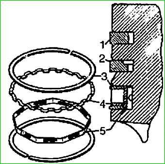
Three grooves are machined on the cylindrical surface of the head, compression rings are installed in the top two, and an oil scraper is installed in the bottom.
The groove for the oil scraper ring has slots on both sides to prevent the rubbing surfaces of the piston skirt from overheating from the heat coming from the piston bottom
The same slots carry oil into the engine crankcase, which is removed by the oil scraper ring
Under the groove for the oil scraper ring there is a chamfer and on it there are two holes on both sides, which also serve to drain the oil that accumulates under the oil scraper ring.
The piston skirt is oval in cross section and barrel-shaped in longitudinal section.
The major axis of the oval is located in a plane perpendicular to the piston pin axis.
The piston ovality is 0.39-0.43 mm.
The largest diameter of the piston skirt is located 8 mm below the piston pin axis.
The diameter of the skirt smoothly decreases both towards the bottom and in the opposite direction, the maximum reduction in diameter at the edge of the chamfer under the bottom groove is 0.034-0.064 mm, at the lower edge of the supporting part of the skirt - 0.050-0.080 mm.
The axis of the hole for the piston pin is shifted from the middle plane by 1.5 mm to the right (along the direction of the car) side, to reduce the noise from shifting the piston from one wall of the liner to another when changing the direction of movement of the piston (up - down).
A steel thermostatic insert is poured into the piston body between the lower groove and the hole for the piston pin, which serves to reduce the deformation of the piston when heated to operating temperature and reduce the initial installation gaps during assembly
Pistons are installed in sleeves of the same size group with a gap of 0.024—0,048 mm
To ensure the required clearance, the pistons and liners are divided (by diameter) into five groups, designated by the corresponding letter, which is stamped on the piston bottom and applied to the outer surface, the lower part of the liner.
To improve running-in, the piston surface is coated (electrolytically) with a layer of tin 0.001-0.002 mm thick.
For pistons to work correctly, they must be installed in the cylinders in a strictly defined position.
To do this, on one of the piston bosses there is the inscription “FRONT”, according to this inscription the piston with the indicated side must be facing the front of the engine
Size groups for the ZMZ-4063 engine
Group "A" (value):
- - piston diameter (skirt) - 92,000-91,988 mm;
- - cylinder diameter - 92.036-93.024 mm
Group "B" (nominal value):
- - piston diameter (skirt) - 92.012-92.000 mm;
- - cylinder diameter - 92.048-92.036 mm
Group "B" (nominal value):
- - piston diameter (skirt) - 92.024-92.012 mm;
- - cylinder diameter - 92.060-92.048 mm
Group "G" (nominal value):
- - piston diameter (skirt) - 92.036-92.024 mm;
- - cylinder diameter - 92.072-92.060 mm
Group "D" (value):
- - piston diameter (skirt) - 92.048-92.036 mm;
- - cylinder diameter - 92.084-92.072 mm
Group "A" (repair magnification 0.5):
- - piston diameter (skirt) - 92.500-91.488 mm;
- - cylinder diameter - 92.536-92.524 mm
Group "B" (repair magnification 0.5):
- - piston diameter (skirt) - 92.512-92.500 mm;
- - cylinder diameter - 92.548-92.536 mm
Group "B" (repair increase 0.5):
- - piston diameter (skirt) - 92.524-92.512 mm;
- - cylinder diameter - 92.560-92.548 mm
Group "G" (repair magnification 0.5):
- - piston diameter (skirt) - 92.536-92.524 mm;
- - cylinder diameter - 92.572-92.560 mm
Group "D" (repair magnification 0.5):
- - piston diameter (skirt) - 92.548-92.536 mm;
- - cylinder diameter - 92.584-92.572 mm
Group "A" (repair magnification 1.0):
- - piston diameter (skirt) - 93,000-92,988 mm;
- - cylinder diameter - 93.036-93.024 mm
Group "B" (repair magnification 1.0):
- - piston diameter (skirt) - 93.012-93.000 mm;
- - cylinder diameter - 93.048-93.036 mm
Group "B" (repair increase 1.0):
- - piston diameter (skirt) - 93.024-93.012 mm;
- - cylinder diameter - 93.060-93.048 mm
Group "G" (repair magnification 1.0):
- - piston diameter (skirt) - 93.096-93.024 mm;
- - cylinder diameter - 93.072-93.060 mm
Group "D" (repair magnification 1.0):
- - piston diameter (skirt) - 93.048-93.036 mm;
- - cylinder diameter - 93.084-93.072 mm
Piston rings
Compression rings are cast from cast iron, the upper one is made from high-strength cast iron, which has o high elasticity, the lower one is made of gray cast iron
The upper compression ring operates under the most severe conditions at high temperatures and pressures, as well as lack of lubrication).
To increase wear resistance, its outer surface adjacent to the cylinder is coated with a layer of chromium.
The chromium layer significantly increases the service life of the top ring. This also helps to increase the service life of the lower cylinder ring.
The outer cylindrical surface of the lower compression ring is coated with a layer of tin 0.006-0.012 mm thick (or the entire surface of the ring has a phosphate coating), which improves its running-in
On the inner cylindrical surface of the lower compression ring there is a recess, thanks to which new rings installed in the cylinder turn out slightly and come into contact with the cylinder only with the edge
This speeds up and improves the running-in of the rings to the cylinder bore.
The ring must be installed on the piston with the recess upward; violation of this condition causes a sharp increase in oil consumption and engine smoke
The upper ring does not have a groove
Oil ring - assembled, four- or three-element.
The four-element ring consists of two steel annular disks 3 and two steel expanders: axial 4 and radial 5
The three-piece oil scraper ring consists of two steel ring discs and one steel dual-function expander
The working cylindrical surface (adjacent to the cylinder) of the annular disks is coated with a layer of chromium 0.080-0.130 mm thick.
Height of compression rings - 2 mm, oil scraper assembly - 4.9 mm Ring lock - straight
Floating-type piston pins (they are not fixed to either the piston or connecting rod) are made of low-alloy steel by cold heading.
The outer surface of the finger is carbon-saturated to a depth of 1-1.5 mm and hardened by high-frequency heating to a hardness of HRC 59-66.
The outer diameter of the pin is 25 mm
To prevent finger knocking, they are matched to the pistons with the minimum clearance allowed by lubrication conditions
Since the linear expansion of the piston material is approximately 2 times greater than that of the pin, at room temperature the pin fits into the holes of the piston bosses with interference
The pin is selected to the connecting rod with a gap of 0.0045 to 0.0095 mm
For ease of selection, pins, connecting rods and pistons are divided into size groups.
Size groups of pistons, connecting rods and fingers of engines of the ZMZ-406 family
Finger diameter - 22.0000-21.9975 mm:
- - holes in the upper head of the connecting rod - 22.0070-22.0045 mm;
- - holes in the piston boss - 22.0000-21.9975 mm;
- - pin, connecting rod and piston markings - white;
- - piston marking “I”
Finger diameter - 21.9975-21.9950 mm:
- - holes in the upper head of the connecting rod - 22.0045-22.0020 mm;
- - holes in the piston boss - 21.9975-21.9950 mm;
- - marking of pin, connecting rod and piston - green;
- - piston marking “II”
Finger diameter - 21.9950-21.9925 mm:
- - holes in the upper head of the connecting rod - 22.0020-21.9995 mm;
- - holes in the piston boss - 21.9950-21.9925 mm;
- - marking of the pin, connecting rod and piston - yellow;
- - piston marking “III”
Finger diameter - 21.9925-21.9900 mm:
- - holes in the upper head of the connecting rod - 21.9995-21.9970 mm;
- - holes in the piston boss - 21.9925-21.9900 mm;
- - marking of the pin, connecting rod and piston - red;
- - piston marking “IV”
Size groups of pistons, connecting rods and fingers of engines of the ZMZ-405 family
Finger diameter - 25.0000-24.9975 mm:
- - holes in the upper head of the connecting rod - 25.0070-25.0045 mm;
- - holes in the piston boss - 25.0000-24.9975 mm;
- - pin, connecting rod and piston markings - white;
- - piston marking “I”
Finger diameter - 24.9975-24.9950 mm:
- - holes in the upper head of the connecting rod - 25.0045-25.0020 mm;
- - holes in the piston boss - 24.9975-24.9950 mm;
- - marking of pin, connecting rod and piston - green;
- - piston marking “II”
Finger diameter - 24.9950-24.9925 mm:
- - holes in the upper head of the connecting rod - 25.0020-24.9995 mm;
- - holes in the piston boss - 24.9950-24.9925 mm;
- - marking of the pin, connecting rod and piston - yellow;
- - piston marking “III”
Finger diameter - 24.9925-24.9900 mm:
- - holes in the top head connecting rod - 24.9995-24.9970 mm;
- - holes in the piston boss - 24.9925-24.9900 mm;
- - marking of the pin, connecting rod and piston - red;
- - piston marking “IV”
The pin is held in the piston by two retaining rings made of round spring wire with a diameter of 2 mm. The rings have a tendril bent to the side.
The retaining rings are installed using pliers so that the tendril faces outward
Connecting rods are forged steel with an I-section rod. A thin-walled tin bronze bushing is pressed into the piston head of the connecting rod.
The crank head of the connecting rod is detachable.
The crank head cover is attached to the connecting rod with two bolts with a ground seat.
The cap bolts and connecting rod bolt nuts are made of alloy steel and heat treated.
The nuts of the connecting rod bolts are tightened to a torque of 68-75 Nm (6.8-7.5 kgf-m) and secured with sealant.
The connecting rod caps are processed together with the connecting rod and therefore cannot be moved from one connecting rod to another.
To prevent possible errors, the serial numbers of the cylinders are stamped on the connecting rod and on the cover on the bolt boss. They should be located on one side.
In addition, the recesses in the cover and connecting rod for the locking protrusions of the liners must also be on one side.
In the connecting rod rod near the crank head there is a hole with a diameter of 1.5 mm, through which the cylinder mirror is lubricated. This hole should be directed to the right side of the engine, i.e., in the direction opposite to the camshaft.
When assembled correctly, the number “24” stamped on the middle flange of the connecting rod rod, as well as the protrusion on the connecting rod cap, should face the front side of the engine.
To ensure dynamic balance of the engine, the total mass of the piston, piston pin, rings and connecting rod installed in the engine can have a difference between the cylinders of no more than 12 g, which is ensured by selecting parts of the appropriate weight.
In terms of details, the difference in weight can be pistons - 4 g. connecting rods - 18 g. piston pins - 2 g.
To ensure the above difference in the mass of parts in one engine (12 g), the connecting rods are divided into four groups by weight and must be selected for one engine with a difference of no more than 5 g.
The crankshaft is cast from high-strength cast iron, has five bearings, assembled with a flywheel and clutch, dynamically balanced, permissible imbalance - no more than 35 g cm).
The diameter of the main journals is 64 mm, connecting rod journals are 58 mm.
The connecting rod journals are hollow.
The cavities in the connecting rod journals are closed with threaded plugs and are intended for additional purification of the oil entering the connecting rod journals.
Under the influence of centrifugal forces arising during rotation of the crankshaft, metal particles of wear products contained in the oil are deposited in the cavities of the connecting rod journals.
Oil is supplied to the crankpin cavities through the holes in the shaft cheeks from the annular groove on the crankshaft main journal liners.
Oil comes to the main journals from the oil line through channels in the block partitions
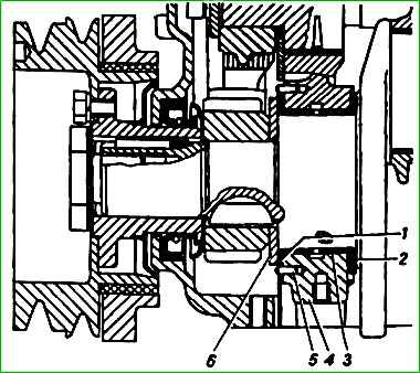
Axial movement of the crankshaft is limited by two thrust steel-aluminum washers 1 and 2 located on both sides of the front main bearing.
The front washer 1 with an antifriction layer faces the steel thrust washer 6 on the crankshaft, the rear washer 2 faces the crankshaft cheek.
The front washer is kept from rotating by two pins 5 pressed into the block and the main bearing cap.
The protruding ends of the pins fit into the grooves of the washer.
The rear washer is kept from rotating by its protrusion, which fits into a groove at the rear end of the main bearing cap.
The axial clearance is 0.125-0.325 mm.
At the front end of the crankshaft, a steel thrust washer, camshaft drive gears, an oil deflector, and a crankshaft pulley hub are mounted on splines.
All these parts are tightened with a bolt screwed into the front end of the crankshaft.
The keyway in the pulley hub is sealed with a rubber plug.
A crankshaft pulley is attached to the hub with six bolts, from which the fan, water pump impeller and generator pulley are driven by two belts.
A special device is mounted on the pulley - a damper, which serves to dampen torsional vibrations of the crankshaft, thereby reducing noise and facilitating the operating conditions of the camshaft drive gears.
The damper consists of a cast iron disk pressed through an elastic (rubber) gasket on the cylindrical projection of the crankshaft pulley
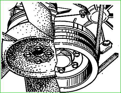
There is one mark on the crankshaft pulley and three marks on the damper disc (Fig. 3), which are used to determine top dead center (TDC) and set the ignition.
The mark on the pulley and the third mark on the damper disk must be opposite each other. Mutual mixing of marks indicates failure of the damper.
When aligned with the indicator rib on the timing gear cover of the third mark in the direction of rotation on the damper disk, the pistons of the first and fourth cylinders are at TDC.
The second mark corresponds to the 5 deg position. to TDC and serves together with the third mark for setting the ignition when the engine is not running.
The first mark corresponds to the position of 12 degrees before TDC and serves together with the second and third marks to monitor the correct installation of the ignition on a running engine.
The front end of the crankshaft is sealed with a rubber seal with an oil deflector pressed into the camshaft cover.
The oil deflector has: a flange that drains oil flowing down the wall of the cover. To facilitate the operation of the cuff, another oil deflector is installed in front of it on the crankshaft.
Reliable operation of the cuff after reassembly is ensured by good alignment of the timing gear cover.
The rear end of the crankshaft is sealed with a packing made of asbestos cord, impregnated with an antifriction compound and coated with graphite.
The packing is placed in the grooves of the cylinder block and a special holder that is attached to the block with two studs
There is a microscrew on the crankshaft journal under the packing, and in front of the packing there is a ridge that serves to throw oil out of the seal area.
The joints of the holder are sealed with L-shaped rubber gaskets.
At the rear end of the crankshaft there is a bored socket for installing the ball bearing of the gearbox input shaft
The flywheel is cast from gray cast iron. It is attached to the flange at the rear end of the crankshaft with four ground bolts
The tightening torque of the bolt nuts is 76-83 Nm (7.6-8.3 kgf m). The nuts are secured with a bending plate.
A toothed rim is pressed onto the flywheel to start the engine with a starter. Before assembly with the crankshaft, the flywheel is statically balanced.