The main brake cylinder, with two sequential pistons 10 and 17 and a two-section reservoir 4 with sensor 6 for an emergency brake fluid level drop indicator, is attached to the cover of the vacuum booster
The brake master cylinder creates pressure in two independent hydraulic circuits.
The volume of brake fluid between pistons 10 and 17 is used to operate the rear brake mechanisms, and the volume of fluid between piston 17 and the end of the plug 20 is used to operate the front brake mechanisms.
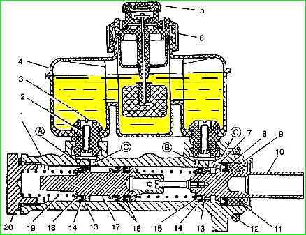
When braking, moving forward, the primary piston 10 and its cuff 15 cover the compensation hole “B” connecting the primary cavity of the master cylinder with the reservoir.
The spring installed between the pistons 10 and 17 is stronger than the spring 19 located between the piston 17 and the plug 20, therefore, simultaneously with the primary piston 10, the secondary piston 17 begins to move, blocking the compensation hole “A” with a cuff, connecting the secondary cavity of the cylinder with tank.
Further movement of the pistons is accompanied by an increase in pressure in the cavities, and, consequently, both brake circuits are activated.
When the force is removed from the brake pedal, the pistons return to their original position under the action of springs.
In this case, compensation holes “A” and “B” open and the liquid in both cavities of the main cylinder communicates with the liquid in the tank, and the pressure in the circuits decreases to atmospheric pressure.
If the brake pedal is released abruptly, the pistons of the master cylinder quickly return to their original position and are ready for subsequent braking.
The rapid return of the pistons is ensured by the fact that when they return to their original position, a vacuum is created in the cavities of the main cylinder, under the influence of which the liquid from the tank through the bypass holes “C” and the holes in the pistons, pressing the washers 13 and the edges of the cuffs 14, enters cavity of the master cylinder.
When the pistons reach their original position, excess fluid from each cavity will flow into the tank through compensation holes “A” and “B.”
If one of the drive circuits fails, fluid leaks from the cavity of the master cylinder connected to the faulty circuit.
If the rear circuit is faulty, then the piston 10 reaches the spring holder 16 and through it acts on the secondary piston 17, which creates pressure in the secondary cavity of the master cylinder and the front circuit.
If the front brake circuit fails, piston 17 acts on the end of plug 20, and piston 10, compressing the spring, displaces fluid from the primary cavity of the master cylinder into the circuit going to the brake mechanisms of the rear wheels.
If one of the drive circuits fails, the brake pedal travel increases, but fairly effective braking of the vehicle is ensured.
If the circuits are in good condition, the brake fluid level in the master cylinder reservoir should be between the MAX and MIN marks.
The gradual change in fluid level from MAX to MIN is associated with wear of the brake linings.
A sharp drop in the level of brake fluid in the reservoir indicates a violation of the tightness of the brake system.
At this point, the brake fluid level alarm is activated and a red lamp on the instrument cluster lights up.
In this case, fluid should be added only after the system’s tightness has been restored.
To check the serviceability of sensor 6 for an emergency drop in the liquid level in the tank, with the ignition on, press on top of the central part of the protective cap 5. In this case, the lamp on the instrument cluster should light up.
Disassembly and assembly of the brake master cylinder
Remove the brake master cylinder. (See the article - How to remove and install the main brake cylinder of a Gazelle car).

Remove the sealing ring.

Use a 38" wrench or socket to unscrew the master cylinder cap

Remove the plug together with the sealing ring

Remove the spring

Squeeze the locking ring with pliers

Remove it.

Use the shank to remove the rear circuit piston along with the outer cuff and guide sleeve.

To remove the cuff from it, unscrew the spring holder screw.

Remove the front circuit piston by pushing it with your finger from the thread side, and remove the separating collars by carefully prying them off with a thin screwdriver.

We wash all parts in clean brake fluid or isopropyl alcohol
Assemble the brake master cylinder in reverse order.
We install new cuffs as shown in the figure.

Tighten the primary piston spring holder screw until it stops.
WARNING: Do not wash brake system parts with gasoline, acetone or other solvents that damage rubber seals.
Before installing new parts, wash off the preservation lubricant from them. You can wash it with alcohol or brake fluid.
")

")
")
")
")
")
")
")