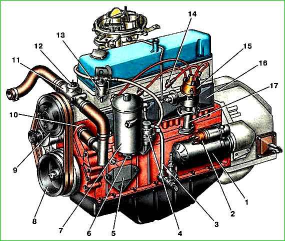
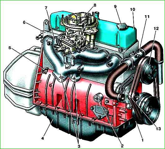
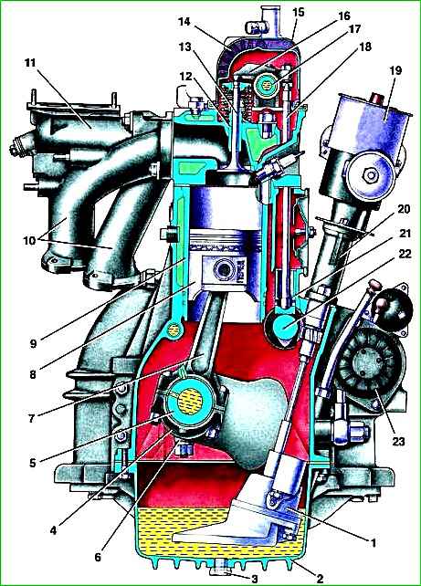
The cylinder block is cast from aluminum alloy and is integral with the upper part of the crankcase.
The block has a water jacket cavity that is open upward, into which cast iron sleeves are inserted with support in the bottom of this cavity
Ten bosses for attaching the cylinder head are located along the contour of the upper plane of the block.
The lower (crankcase) part of the block is divided into four compartments by transverse partitions into which the crankshaft main bearings are installed.


The cylinder block is cast from aluminum alloy and is integral with the upper part of the crankcase.
The block has a water jacket cavity that is open upward, into which cast iron sleeves are inserted with support in the bottom of this cavity.
Ten bosses for attaching the cylinder head are located along the contour of the upper plane of the block.
The lower (crankcase) part of the block is divided into four compartments by transverse partitions into which the crankshaft main bearings are installed.
The main bearing caps are made of ductile iron; each cover is attached to the block with two studs with a diameter of 12 mm.
In the first cover, the ends are processed together with a block for installing thrust bearing washers.
The bearing caps are bored together with the block, and therefore, during repairs, they must be installed in their places. to facilitate installation, all covers, except the first and fifth, have their serial numbers stamped on them.
The nuts of the studs securing the covers are tightened with a torque wrench with a torque of 100-110 Nm (10-11 kgcm) and locked with Unigerm-9 sealant.
Attached to the front end of the block on a paronite gasket is a timing gear cover cast from aluminum alloy with a rubber collar to seal the crankshaft toe.
A clutch housing cast from aluminum alloy is attached to the rear end of the block with six bolts and two dowel pins, the precise installation of which is necessary for proper operation of the gearbox.
The rear end of the clutch housing and the hole in it for installing the gearbox in order to ensure alignment of the gearbox input shaft with the crankshaft are processed as an assembly with the block, so these parts are not interchangeable.
The engine cylinders are made in the form of easily removable wet liners cast from special wear-resistant cast iron.
The cylinder liner is inserted into the block socket with the lower part.
In the plane of the lower joint, the liner is sealed with a soft copper gasket 0.3 mm thick, and along the upper end - with a cylinder head gasket.
For proper compaction, the upper end of the sleeve protrudes above the plane of the block by 002-0.1 mm.
In this case, the copper gasket must be crimped.
For a reliable seal, it is necessary that the difference in the protrusion of the sleeves above the plane of the block on one engine be within the range of 0.02-0.055 mm This is achieved (at the factory) by sorting cylinder liners by height (from the bottom joint to the top end) and blocks by the depth of the groove under the liner (from its top end) into two groups.
When changing cylinder liners, uniform protrusion can be ensured by selecting copper spacers of the appropriate thickness.
The cylinder head is common to all cylinders, cast from an aluminum alloy and subjected to heat treatment (hardening and aging).
Intake and exhaust ports are made separately for each cylinder and are located on the right side of the head.
The valve seats are arranged in a row along the longitudinal axis of the engine.
The seats of all valves are plug-in, made of high-hardness heat-resistant cast iron.
Due to the large tension when fitting the seat into the head socket (at the factory, before assembly, the head is heated to a temperature of 160-175 ° C, and the seats are cooled to approximately minus 40-45 ° C, while the seat is freely inserted into the head socket), and Also, the sufficiently large coefficient of linear expansion of the seat material ensures a reliable and strong fit of the seat in the socket.
Additionally, the metal of the head is crimped around the seats using a mandrel.
Valve bushings, like the seats, are assembled with the head preheated (the bushings are cooled).
Chamfers in the seats and holes in the bushings are machined together with the head.
The cylinder head is attached to the block with ten steel studs with a diameter of 12 mm. Flat steel heat-strengthened washers are placed under the stud nuts.
A gasket made of asbestos sheet reinforced with a metal frame and coated with graphite is installed between the head and the block.
The windows in the gasket for the combustion chambers and the oil channel opening are edged with tin.
The thickness of the gasket in the compressed state is 1.5 mm.
The correct position of the head on the block is ensured by two alignment pins-bushings pressed into the cylinder block (into the bosses of the head mounting studs).
The tightening torque of the cooker fastening nuts should be 83-90 Nm (8.3-9.0 kgcm).
The cylinder heads of the 4025 and 4026 engines differ in the volume of the combustion chambers.
The increase in the compression ratio of the 4026 engine was achieved by additional milling of the lower plane of the head by 3.6 mm (the height of the 4026 engine head is 94.4 mm, the height of the 4025 engine head is 98 mm).
The volume of the combustion chamber with the valves in place and the spark plug screwed in is 74-77 cm for the 4026 engine and 94-98 cm for the 4025 engine. The difference between the volumes of the combustion chambers should not exceed 2 cm 2


