Clean all mating surfaces of the block from gaskets stuck and torn during disassembly
Attach the cylinder block to the stand, carefully inspect the cylinder mirror, if necessary, remove the unworn belt above the upper compression ring with a scraper. The metal should be removed flush with the worn surface of the cylinder.
Remove the oil channel plugs and blow out all oil channels with compressed air. Screw the plugs into place.
Assemble the crankshaft by unscrewing the plugs of the dirt traps of the connecting rod journals and removing deposits from them, rinsing and blowing with air, putting the plugs in place, tightening them to a torque of 37-51 N⋅m (3.8-5.2 kgf⋅m).
For reliable locking, apply Stopor-9 anaerobic sealant to the threads of the plugs.
Check the condition of the working surfaces of the crankshaft. Nicks, burrs and other external defects are not allowed.
Wipe the bed under the liners in the block and in the main bearing caps with a napkin.
Install the upper main bearing shells (with grooves and holes) in the block bed, and the lower ones (without grooves) in the cover bed, wipe the bearings with a napkin and lubricate them with engine oil.
Wipe the main and connecting rod journals of the crankshaft with a napkin, lubricate them with clean oil and install the crankshaft into the cylinder block.
Lubricate and install the thrust bearing half washers:
- upper - in the grooves of the third main bed with an anti-friction layer with grooves to the cheek of the crankshaft;
- lower - together with the cover of the third main bearing. The protrusions of the lower half washers should fit into the grooves of the cover;
Install the covers of the remaining supports on the corresponding main journals, screw in and tighten the bolts securing the main bearing covers to a torque of 98-107.9 N⋅m (10-11 kgf⋅m).
On the lower surfaces of the 1st, 2nd and 4th main caps their serial numbers are stamped.
On the lower surface of the third main support cover there is a threaded hole for attaching the oil pump holder, and on the side surfaces there are grooves and grooves for installing half washers.
The covers of the main supports are installed according to their numbering, oriented so that the grooves for the liner lug in the cover and the block are located on one side.
Rotate the crankshaft, its rotation should be free with little effort.
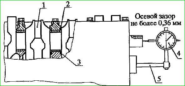
Check the axial clearance of the crankshaft (Figure 1), which should be no more than 0.36 mm. For unworn crankshaft and thrust bearing half washers, the clearance is 0.06-0.27 mm.
If the axial clearance exceeds the maximum permissible value, replace the thrust half washers with new ones and measure the axial clearance again. If during measurement it turns out to be more than 0.36 mm, replace the crankshaft.
Take the oil seal holder with the oil seal at the rear end of the crankshaft, check the suitability of the oil seal for further work.
If the oil seal has worn working edges or weakly covers the crankshaft flange, replace it with a new one.
It is recommended to press the oil seal into the oil seal holder using a mandrel.
The oil seal must be installed with the boot on the outside of the engine, the working edge covered by the spring inward.
Before pressing, apply Litol-24 lubricant to the outer surface of the oil seal to facilitate pressing.
Fill ⅔ of the cavity between the working edge and the boot of the rubber cuff with CIATIM-221 lubricant, install and secure the oil seal holder with the gasket to the cylinder block.
Install the flywheel onto the rear end of the crankshaft, aligning the pin hole in the flywheel with the locating pin pressed into the crankshaft flange.
Install the washer of the flywheel bolts, attach and tighten the bolts to a torque of 70.6-78.4 N⋅m (7.2-8.0 kgf⋅m).
Press the spacer sleeve and bearing into the flywheel seat. Press the bearing in, applying force to the outer ring. Pressing into the inner ring will damage the bearing.
Next, we assemble the connecting rod and piston group - article How to assemble the connecting rod and piston group of the ZMZ-40524 engine
Attach the holder to the oil pump.
Install the oil pump with the gasket on the mating surface of the cylinder block and secure it.
Cut off the protruding ends of the chain cover gaskets and oil seal holder gaskets protruding above the plane of the block, chain cover and oil seal holder.
Install and secure the oil pan with gasket and clutch housing booster.
Lubricate the intermediate shaft bushings and lips with engine oil Replace the segment key into the groove at the end of the intermediate shaft and install the intermediate shaft into the cylinder block.
Screw two bolts into the front flange of the intermediate shaft.
Install the gear with the nut on the rear end of the shaft, aligning the keyway of the gear with the key, and rotating the intermediate shaft using two bolts, tighten the gear nut until it stops.
Install and secure the intermediate shaft flange.
Lubricate the oil pump drive shaft and gear teeth with engine oil and insert the roller into the hole in the block until the oil pump drive gears and the intermediate shaft engage.
Insert the hexagonal shaft of the oil pump drive into the hole in the drive shaft bushing so that it fits into the hexagonal hole of the oil pump shaft.
Install and secure the oil pump drive cover with gasket.
Check that the intermediate shaft rotates easily. The shaft should rotate freely, without jamming.
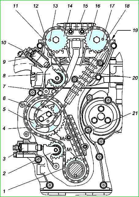
Installing the camshaft drive (Figure 2):
Press the segment key into the keyway of the front end of the crankshaft.
Using a special tool, press the sprocket onto the engine crankshaft, with the mark facing forward.
Install the rubber O-ring into the groove at the front end of the crankshaft.
Rotate the engine crankshaft until the mark on the crankshaft sprocket coincides with the “M1” mark on the cylinder block, which will correspond to the position of the piston of the first cylinder at TDC.
In this case, the mark on the cylinder block should be located symmetrically relative to the axis of the sprocket teeth cavity.
Install the lower chain guide without completely tightening the fastening bolts, having first applied anaerobic sealant "Stopor - 6" to the bolt threads.
Place the lower chain onto the driven sprocket (38 teeth) of the intermediate shaft and onto the engine crankshaft sprocket.
Install the sprocket with the chain on the intermediate shaft, while the mark on the driven sprocket of the intermediate shaft must coincide with the "M2" mark on the cylinder block, and the drive branch of the chain passing through the damper must be tensioned.
Install the intermediate shaft drive sprocket with a pin and secure both sprockets to the intermediate shaft with bolts with a torque of 24.5-26.5 N⋅m (2.5-2.7 kgf⋅m). Bend the two corners of the locking plate on the edges of the bolt heads.
Install the tensioner lever with the sprocket of the lower camshaft drive chain and secure it with the lever bolt, having previously applied Stopor-6 anaerobic sealant to the bolt threads.
Applying an excessive amount of sealant will cause it to be squeezed out of the thread and the tensioner lever will become immobilized on the axis.
Pressing the tensioner lever, tension the chain, check that the sprockets are installed correctly according to the marks and tighten the bolts of the lower damper.
After installing the lower chain, rotation of the crankshaft is not allowed until the camshaft drive chain and hydraulic tensioners are installed.
Install the bolt support for the tensioner lever and secure it with bolts, having previously applied Stopor-6 anaerobic sealant to the bolt threads
Install the tensioner lever with the sprocket of the upper camshaft drive chain and secure the lever bolt to the support, having previously applied Stopor-6 anaerobic sealant to the bolt threads.
Place the upper camshaft drive chain onto the intermediate shaft drive sprocket.
Apply Unisil H50-1 silicone adhesive-sealant to the cylinder block around the installation sleeve of the chain cover on the right side of the block (inside which there is an oil supply channel to the lower hydraulic tensioner).
Take the chain cover with the oil seal and check the suitability of the oil seal for further work.
If the oil seal has a worn working edge or weakly covers the hub of the damper pulley, replace it with a new one.
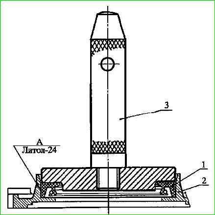
It is recommended to press the oil seal into the chain cover using a mandrel (Figure 3).
The oil seal must be installed with the boot on the outside of the engine, the working edge covered by the spring - inward.
Before pressing, apply Litol-24 lubricant to the outer surface of the oil seal to facilitate pressing.
Fill the cavity between the working edge and the boot of the rubber cuff of the chain cover with CIATIM-221 lubricant.
Keeping the second stage chain from jumping off the intermediate shaft sprocket, install and secure the chain cover with gaskets and the generator bracket.
Install and secure the water pump with the electromagnetic clutch and gasket to the chain cover by tightening the bolt securing the water pump to the chain cover.
Lubricate the hole for the hydraulic tensioner in the chain cover with clean motor oil used for the engine and install the assembled hydraulic tensioner until the tensioner lever touches the stop, but do not press, in order to prevent the hydraulic tensioner lock from operating.
Install a noise-insulating washer into the cover, close the hydraulic tensioner with a cover with a gasket, insert the bolts (the lower bolt with the bracket for fastening the synchronization sensor wire) and tighten the cover bolts.
Use a mandrel through the hole in the hydraulic tensioner cover to press the hydraulic tensioner, moving it until it stops, then release it, in which case the retaining ring on the plunger will disengage with the hydraulic tensioner body and allow the plunger and body to move under the action of the spring.
The body will move all the way, and the chain will be tensioned through the tensioner lever.
Screw the plug into the hydraulic tensioner cover, having previously applied Stopor-6 anaerobic sealant to the threads of the plug.
Cut off the ends of the chain cover gaskets protruding above the plane of the cylinder block and chain cover.
If there are no rubber seals on the cylinder head gasket in two places that lie at the joints of the chain cover with the cylinder block, silicone adhesive-sealant "Unisil N50-1" should be applied to these places of the gasket (windows).
Install the cylinder head gasket onto the cylinder block pins and chain cover studs.
Install a hose connecting the water pump pipe to the thermostat housing onto the water pump connection.
Install the assembled cylinder head onto the cylinder block and secure it.
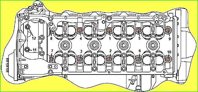
Tighten the cylinder head mounting bolts in the sequence shown in Figure 4, in two stages: first tighten the bolts to a torque of 40.-50 N⋅m (4.0-5.0 kgf⋅m), then hold for at least 1.2 minutes and finally tighten the bolts at an angle of 90°.
Before installation, lubricate the bolt threads with engine oil. Tighten bolts No. 11, 12 to a torque of 19.6-24.5 N⋅m (2.0...2.5 kgf⋅m).
To avoid water hammer when tightening the bolts and the occurrence of cracks in the cylinder block, there should be no oil in the threaded wells of the block.
Unscrew the bolts and remove the camshaft covers, wipe the bed under the camshafts in the head and in the covers with a napkin, and before installing the covers, lubricate the threads of the bolts with clean engine oil.
Lubricate the holes in the head for the hydraulic pushers with engine oil and install the hydraulic pushers into the cylinder head.
When repairing an engine without replacing the hydraulic tappets, they should be installed in accordance with their location before disassembly.
If the hydraulic pusher fails, it must be replaced, since it cannot be repaired. The hydraulic pushers must be removed using a suction cup or a magnet.
Install the camshafts on the cylinder head, having previously lubricated the beds in the head with engine oil.
The intake camshaft is installed with the sprocket pin facing up, and the exhaust camshaft is installed with the sprocket pin facing to the right. Due to the angular arrangement of the cams, these camshaft positions are stable.
Lubricate the shaft bearing journals with clean engine oil used in the engine.
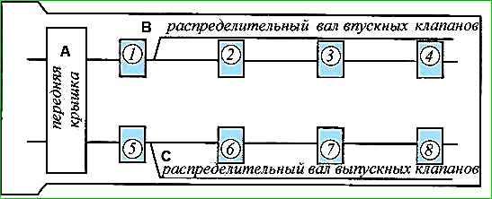
Camshaft covers must be installed according to their numbering (Fig.no. 5), guided by round bosses with numbers for the intake shaft - to the left, exhaust - to the right, when viewed from the front end of the engine.
This orientation is associated with the asymmetrical location of the oil channel groove in the covers.
Install the front camshaft cover with the thrust flanges installed in it onto the installation sleeves, and ensure that the thrust flanges are installed in the grooves by means of the longitudinal movement of the camshafts.
Before installation, lubricate the thrust flange with clean engine oil used in the engine.
Install covers No. 3 and No. 7 of the camshafts and pre-tighten the bolts securing the covers until the surface of the covers comes into contact with the upper plane of the cylinder head.
Install all other covers in accordance with the markings and pre-tighten the cover bolts.
Finally tighten the camshaft cover bolts to a torque of 18.6-22.6 N⋅m (1.9-2.3 kgf⋅m).
Lubricate all camshaft cams with engine oil and check the rotation of each camshaft in the supports by turning the camshaft with a wrench using a special square on the camshaft until the valve springs of one of the cylinders are fully compressed.
With further rotation, the camshaft should rotate independently under the action of the valve springs until it touches the next cams with pushers.
After checking the ease of rotation of the camshafts, rotate them so that the alignment pins for the sprockets are approximately horizontal and directed in different directions (Figure 2).
These camshaft positions are stable and are ensured by the angular arrangement of the cams.
Start setting the angular position of the camshafts from the exhaust shaft; to do this, throw a drive chain over the sprocket, install the sprocket on the flange and pin of the camshaft, and to align the pin and the hole on the sprocket, turn the camshaft clockwise by the square.
Tighten the drive chain by turning the camshaft counterclockwise until the mark on the sprocket aligns with the upper plane of the cylinder head. The crankshaft must not be allowed to turn.
To angularly install the intake camshaft, place the drive chain over the sprocket, install the sprocket on the flange and the camshaft pin with the chain branch between the sprockets slightly slack.
Tighten the chain by turning the camshaft counterclockwise until the mark on the sprocket aligns with the upper plane of the cylinder head.
Install and tighten the sprocket mounting bolts to a torque of 54.9-60.8 N⋅m (5.6-6.2 kgf⋅m), holding the camshafts from turning the camshafts with a key at the square.
Install the hydraulic tensioner for the upper camshaft drive chain in the same way as installing the hydraulic tensioner for the lower chain.
Install the middle and upper chain guides, tighten the fastening bolts without completely tightening them, having first applied Stopor-6 anaerobic sealant to the bolt threads.
Turn the working branches of the upper chain by turning the engine crankshaft in the direction of rotation and finally tighten the bolts securing the middle and upper chain stabilizers.
Install the bushing on the front end of the crankshaft close to the sprocket, orienting the large internal chamfer towards the sealing ring, and the groove under the end of the key towards the front of the engine.
Press the parallel key into the keyway of the front end of the crankshaft so that its hemispherical end goes all the way into the groove of the bushing.
Using a special tool, press the damper pulley onto the front end of the crankshaft until it stops, aligning the damper pulley keyway with the key.
Tighten the pinch bolt and tighten to a torque of 166.6-215.6 N⋅m (17-22 kgf⋅m).
After assembly is completed, check the installation of the camshafts by turning the engine crankshaft two turns in the direction of rotation until the mark on the crankshaft damper matches the mark on the chain cover. In this case, the marks on the camshaft sprockets must coincide with the upper plane of the cylinder head.
When repairing an engine involving the removal of camshafts, cylinder heads and sprockets on the intermediate shaft, install the camshaft drive during assembly as indicated above.
If the intermediate shaft sprockets and chain cover are not removed during repairs, then before disassembling it is necessary to set the piston of the 1st cylinder to the TDC position on the compression stroke, while the mark on the crankshaft damper pulley must coincide with the protrusion on the chain cover , and the marks on the camshaft sprockets should be located horizontally, directed in different directions and coincide with the upper plane of the cylinder head.
After removing the camshafts and cylinder heads, the crankshaft can only be turned by returning to its original position or by turning the crankshaft by 2 revolutions.
Rotating the crankshaft by 1 revolution, even if the marks on the pulley and the chain cover coincide, will result in incorrect valve timing.
If the camshafts and sprockets are installed incorrectly, the marks on the sprockets will not coincide with the upper plane of the cylinder head. In this case, it is necessary to remove the sprockets, turn the crankshaft 1 revolution in the direction of rotation and repeat the installation of the sprockets as indicated above.
Subsequent operations for assembling the engine
Install and secure the front cylinder head cover with gasket.
Install the thermostat housing into the thermostat hose and secure the thermostat housing with the gasket to the cylinder head, tighten the hose clamps.
Press in the oil level indicator rod tube and install the indicator. To increase the reliability of installation and tightness, first apply Loctite-638 sealant to the surface of the lower end of the tube.
Install the exhaust manifold with gasket onto the cylinder head studs. Install and tighten all but the last manifold mounting nut.
Install the exhaust manifold screen onto the exhaust manifold studs and secure with nuts.
Install the hose connecting the pump to the water intake pipe onto the water pump fitting and secure it with a clamp.
Place the bracket on the water intake tube.
Insert the water intake tube into the hose placed on the water pump fitting and place the bracket on the last pin of the manifold. Secure the bracket by tightening the nut and tighten the hose clamp.
Install the drain plug of the cylinder block, having previously applied silicone adhesive-sealant "Unisil N50-1" or anaerobic sealant "Stopor-6" to the threads of the plug.
Install and secure the valve cover with gasket and spark plug well seals. Install the timing sensor connector holder on the valve cover.
Install and secure the upper and lower generator brackets and the front engine lift bracket at the same time.
Install the coolant intake pipe with a gasket. First apply Stopor-6 anaerobic sealant to the threads of the pipe bolts.
Install and secure the intake pipe with gasket to the cylinder head.
Install the receiver with the gasket onto the studs of the inlet pipe and secure with nuts.
Attach the receiver to the cylinder head using two corner brackets installed on the cylinder head studs.
First, without tightening, tighten the screws securing the brackets to the receiver, then tighten the nuts securing the brackets to the head and tighten the screws securing them to the receiver.
Install the ventilation hose with the ventilation tube and secure with clamps. Install the hose of the small ventilation branch onto the fittings of the ventilation tube and receiver and secure with clamps.
Install and secure the driven and pressure plates of the clutch, centering the driven disc using a special mandrel.
The gearbox input shaft can be used as a mandrel. Tighten the pressure plate bolts sequentially in several stages to avoid distortion of the pressure plate to a torque of 19.6-24.5 N⋅m (2.0-2.5 kgf⋅m).
Install the clutch release fork pin and studs into the clutch housing.
Install the clutch housing with the engine lift bracket onto the locating pins of the cylinder block and secure it to the cylinder block with bolts.
Remove the engine from the stand.
Procedure for installing attachments on the engine
- Lubricate the rubber O-rings of the injectors with clean engine oil, install the fuel line with the ends of the injectors into the holes in the intake pipe and secure the fuel line.
- Install the emergency oil pressure indicator sensor into the cylinder head, having previously applied Stopor-6 anaerobic sealant to the threaded part of the sensor.
- Install the generator and secure it. First, tighten the nuts of the bolts securing the generator to the upper and lower brackets, then the bolt securing the bushing of the upper bracket.
- Install the automatic tensioning device so that the pin of the device fits into the hole in the boss of its fastening, and tighten the screw of its fastening, having previously applied Stopor-6 anaerobic sealant to the screw thread.
Then follows:
- move the tensioner roller with a wrench by the roller mounting bolt to its extreme position;
- insert the fixing pin (Ø 4 mm and 55 mm long) into the hole in the tension device until it stops;
- release the roller, with the roller pin in the extreme position;
- put the belt on the pulleys;
- slightly move the roller with a wrench, loosening the pin, and remove the pin using pliers;
- bring the roller to the belt and release the roller. The belt will be tensioned by the tensioner.
- Install phase sensor into the hole in the cylinder head and secure it with a bolt, after lubricating the sensor O-ring with clean engine oil. The sensor flange must fit snugly against the surface of the cylinder head before being secured with a bolt.
- Install the synchronization sensor into the boss hole of the chain cover. Place the sensor wire in a bracket secured by the lower bolt of the lower hydraulic tensioner cover, install the connector in the holder on the valve cover.
- Install the knock sensor and secure with a nut and spring washer with a torque of 20 ± 0.5 N⋅m (2.0 ± 0.05 kgf⋅m).
- Install and secure the throttle with gasket to the receiver.
- Screw in the spark plugs.
When installing spark plugs, take precautions not to damage the threads of the spark plug hole of the cylinder head. The spark plugs should be installed by lightly turning the key and then tightened to a torque of 20.0-30.0 N⋅m (2.1-3.1 kgf⋅m).
- Install the ignition coils and secure with nuts.
- Install the starter and secure with bolts.
- Screw the coolant temperature sensors of the control system and the coolant overheating indicator into the thermostat housing, having previously applied Stopor-6 anaerobic sealant to the threaded part of the sensors.
- Install the thermal valve with the gasket, orienting its fitting upward, and secure the thermal valve with the oil filter fitting.
- Install the oil filter. Before installing the filter, lubricate the rubber filter gasket with clean engine oil. Screw the filter onto the fitting until the gasket touches the supporting surface and then tighten it ¾ of a turn.