The ZMZ-40524.10 engine is a modification of the ZMZ-40522.10 engine in order to meet Euro3 toxicity standards and increase its reliability and service life
ZMZ-40524 engines. 10 are intended for installation on trucks and buses of the GAZelle family with a gross weight of up to 3500 kg and on cars of the Sobol family with a gross weight of up to 2980 kg, produced by GAZ OJSC.
The engines are produced in the “U2” climatic version, intended for operation in temperate climates at ambient temperatures from minus 45°C to plus 40°C and relative air humidity up to 100% at a temperature of plus 25°C.
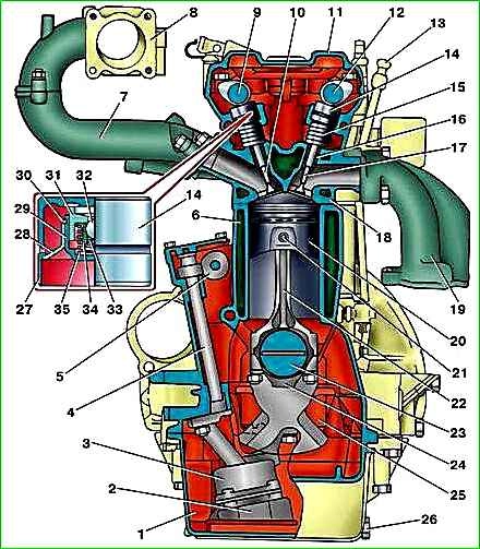
Cross-section of the ZMZ-40524 engine in Figure 1.
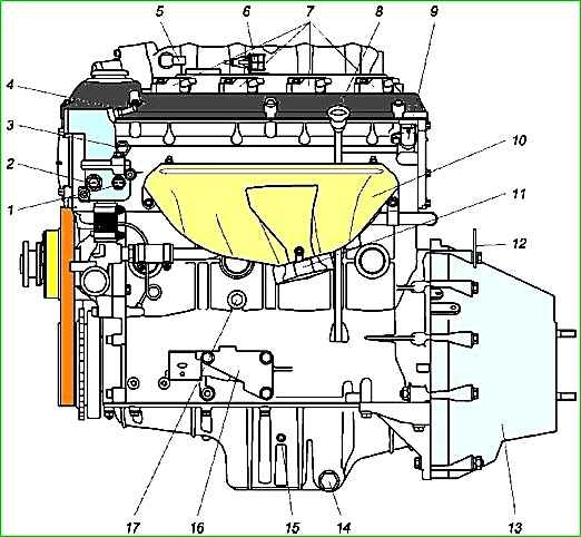
Left side of the ZMZ-40524 engine in Figure 2
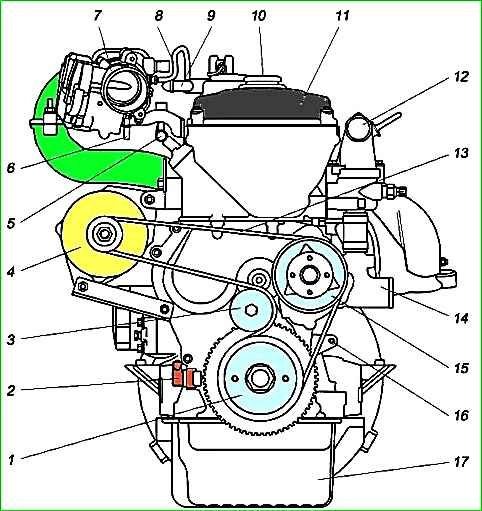
Front view of the ZMZ-40524 engine in Figure 3
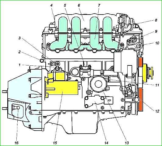
Right side of the ZMZ-40524 engine in Figure 4
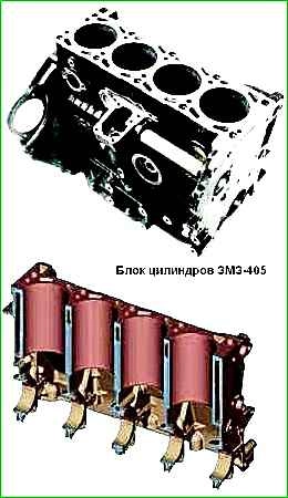
The cylinder block is cast from gray cast iron and is made in the form of a monoblock with the crankcase part lowered below the axis of the crankshaft.
Between the cylinders in the upper part there are ducts made in the casting for passage coolant
There are five main bearing housings located at the bottom of the block.
The main bearing caps, made of high-strength cast iron, are machined together with the cylinder block and therefore are not interchangeable.
On the lower surfaces of the 1st, 2nd and 4th covers their numbers are stamped for correct installation.
When installing covers, the locking grooves for the liners in the cylinder block and in the covers should be located on one side.
Blocks with holes on the cylinder walls, cracks on the upper plane of the block and on the ribs supporting the main bearings, with holes on the water jacket and crankcase are subject to rejection.
As a result of natural wear, the cylinders in the block acquire the shape of an irregular cone in length and an oval in circumference.
Wear reaches its greatest value in the upper part of the cylinders against the upper compression ring, with the piston position at TDC, the smallest in the lower part, with the piston position at BDC.
Cylinders and pistons are divided into five size groups A, B, C, D, D
The letter designating the cylinder group is painted on the left outer side of the block opposite each cylinder.
All cylinders in one block should, as a rule, be processed to the same repair size with a tolerance of +0.036...+0.072 mm from the nominal value, with the exception of cases when it is necessary to remove shallow scratches on the cylinder mirror (within the magnification range cylinder diameter by 0.10 mm), here only defective cylinders can be corrected.
Technical characteristics of the engine and its systems
Petrol engine is four-cylinder, four-stroke, single-row, with an integrated control system for fuel injection, ignition and air intake
Cylinder diameter and piston stroke - 95.5x86 mm
Cylinder displacement - 2464 cm 3
Compression ratio - 9.4
The operating order of the cylinders is 1-3-4-2
The direction of rotation of the crankshaft (from the pulley side) is right
Rated power at rotation speed 4500±50 min -1 gross according to GOST 14846 - 98.0 (133.3) kW (hp)
Maximum torque at rotation speed 4000±200 min -1 gross according to GOST 14846 - 214.0 (21.8) Nm (kgcm)
Power system - Distributed fuel injection by electromagnetic injectors into the intake pipe
Air filter - With dry replaceable filter element (installed on the vehicle)
Ventilation system - Closed, forced, with vacuum valve
Lubrication system - Combined, with automatic oil temperature control
Oil filter - Full-flow, non-separable, fine filter 406.1012005-01 or 406.1012005-02
Cooling system - Liquid, closed, with forced circulation of liquid
Thermostat - two-valve, with an opening temperature of the main valve of 82±2˚ C - TS 107-05 or TP2-01 or TA107-05
Electronic control system - Controls the air supply, distributed fuel injection by electromagnetic injectors into the intake pipe and ignition
Spark plugs - DR17YC/A
Electrical equipment - DC, single-wire, negative terminals of sources and consumers are connected to the motor housing
Rated voltage - 12 V
Generator - with built-in rectifier unit and voltage regulator 5122.3771 or 4052.3701000 (AAK 5572 14U 80A 11.203.412)
Starter - with remote electromagnetic activation and gearbox 6012.3708 or 405.3708000 (AZE2154 12V1.9 kWz9 11.131.262)
coolant overheat indicator sensor - thermistor type TM111-02
emergency oil pressure indicator sensor - contact type 2602.3829 or 4021.3829 or 6012.3829
Clutch - dry, single disc, with diaphragm pressure spring
Pressure in the lubrication system on a warm engine at the installation site of the emergency oil pressure sensor at an idle speed of 850±50 min -1, not less than 98 (1.0) kPa (kgf /cm 2)
The gap between the spark plug electrodes is 0.7-0.85 mm
Operating coolant temperature - 80-110 °C
Minimum crankshaft rotation speed at idle - 850±50 min -1
Increased crankshaft speed - 3150±50 min -1


