Removal of the pressure regulator from the car and its repair are carried out if adjustment cannot achieve its correct operation
To remove the regulator you must:
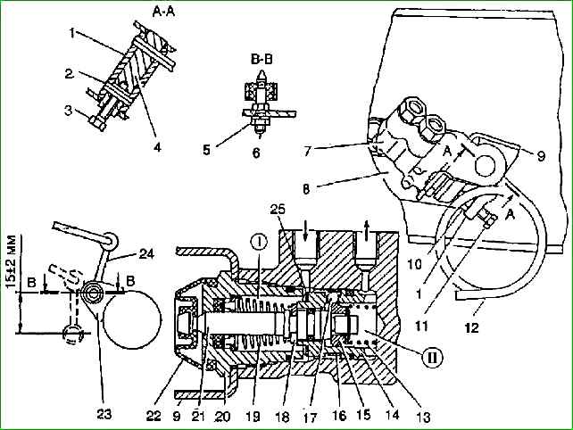
- - disconnect the lower end of the rack 24 (see Fig. 1) from the rear axle bracket (see How to replace and adjust the brake force regulator of a Gazelle car);
- - disconnect the pipelines and plug them with caps of the bleeding valves;
- - disconnect the regulator from bracket 8 by unscrewing the two nuts with spring washers.
Disassembling the pressure regulator must be done in the following order:
- - unscrew bolt 3, remove stop pin 2 and release the end of load spring 12.
Remove axle 4 and remove pressure lever 1, without disturbing the position of adjusting bolt 11 during disassembly;
- - remove the protective cover 22,
- - unscrew the bushing 20 securing the regulator body;
- - remove the return spring 19 and the spring washer, and then remove the piston 21 with the sleeve 14 by the shank and remove the spring 13;
- - remove the pressure spring 16 from the sleeve and remove the ball 17 from the sleeve socket;
- - remove the lock washer of the control cone 15, the flat and spring washer and then the control cone.
The piston should be removed from the liner when necessary to replace faulty parts.
After disassembling, the regulator parts should be washed in alcohol or clean brake fluid, carefully inspected, defective parts replaced, generously lubricated with fresh brake fluid and reassembled in reverse order.
A possible cause of malfunction of the regulator may be insufficient tightness of the ball valve.
In this case, with light blows of a hammer through a copper or aluminum mandrel, you should hammer out the recess in the regulator sleeve with a ball.
The performance of the regulator after assembly should be checked on a special stand with pressure gauges at the inlet and outlet of the regulator and a device that creates pressure.
The fluid pressure at the outlet of the pressure regulator should be approximately 2.8 times lower than the inlet pressure.
When checking, without releasing the specified fluid pressure, smoothly press the load spring 12 to create force on the piston 21.
In this case, the outlet pressure should increase, which indicates proper operation of the regulator.
When a certain force is created, the pressure at the inlet and outlet must be equalized.
Install the tested regulator on the vehicle and adjust the drive.
After installing the regulator, bleed the system and check it on the road
")

")
")
")
")
")
")
")