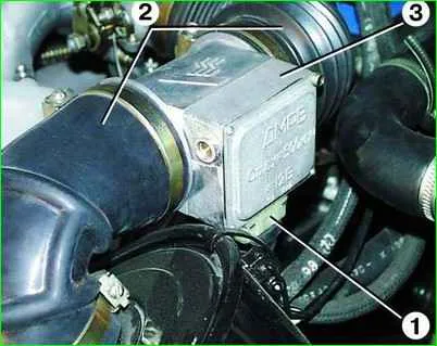
The mass air flow sensor is used to determine the amount of air entering the engine cylinders
Signals from the sensor enter the engine control unit and are one of the parameters that determine the duration of fuel injection by the injectors - the amount of fuel depends on the amount of air at any given moment.
The main element of the sensor is a platinum filament, heated up to 150 °C during operation.
As the air intake from the engine passes through the sensor housing, the filament is cooled, and the electronic circuit of the sensor constantly strives to maintain a filament temperature of 150 °C.
The electrical power expended to maintain the filament temperature is the parameter by which the engine control unit determines the duration of the electrical pulse supplied to the injectors.
The degree of cooling of the platinum filament depends not only on the quantity, but also on the temperature of the passing air, determined by a thermal compensation resistor, which accordingly corrects the signal supplied by the sensor to the control unit.
To make it possible to adjust the amount of carbon monoxide in the exhaust gases at idle speed, the electronic module has a variable resistor, with the screw of which you can manually change the magnitude of the signal supplied by the sensor to the electronic control unit, thereby changing the duration of the pulse supplied to the injectors, and therefore, the amount of fuel injected.
To clean the platinum thread from contaminants, the electronic module periodically supplies it with increased voltage, causing heating to 1000 °C. In this case, all deposits burn out.
If the sensor fails, the engine control unit turns on a backup program that ensures engine operation with slightly different, but acceptable power and consumption characteristics.
At the same time, the warning lamp in the instrument cluster lights up.
Disconnect the wire from the negative terminal of the battery.
Disconnect block 1 from mass air flow sensor 3.
Loosen the clamps, disconnect the air supply hoses 2 and remove the sensor 3.

Install the new sensor in reverse order.
Checking the mass flow sensor
Remove the mass air flow sensor.
Connect a voltmeter to contacts “2” and “3” of the sensor connector.
Apply 12 V direct current to contacts “1” and “5” (“+” to contact “5”, and “–” to “1”).
In this case, the voltmeter should show a voltage of 1.3–1.4 V.
Then briefly close contacts “4” and “5” with each other.
The voltmeter should show a voltage of about 8 V, and the platinum thread should become red-hot.
If at least one of these conditions is not met, replace the sensor.
Also see the article - "Checking and replacing sensors ZMZ-406 GAZ-2705"


