Lever-type clutch - dry, single-plate, consists of a housing assembly with a pressure plate, a clutch release lever, support forks, springs and a driven disk assembly with friction linings
The clutch housing is secured to the crankshaft flywheel with six centering (special) bolts.
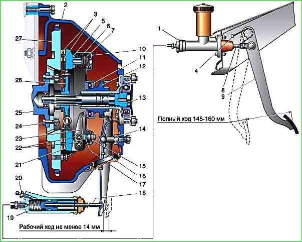
The force of nine double pressure springs creates the necessary friction force on the surfaces of the friction linings and ensures the transmission of torque from the flywheel through the housing and pressure plate to the clutch driven disc and the gearbox input shaft.
The clutch release levers are hinged to the housing using spherical adjusting nuts, through which the ends of the clutch release levers are also installed in the same plane.
At the factory, the clutch drive plate is balanced as an assembly with the crankshaft and engine flywheel, so when removing and installing it, it is necessary to align the marks (0) on the flywheel and the clutch housing.
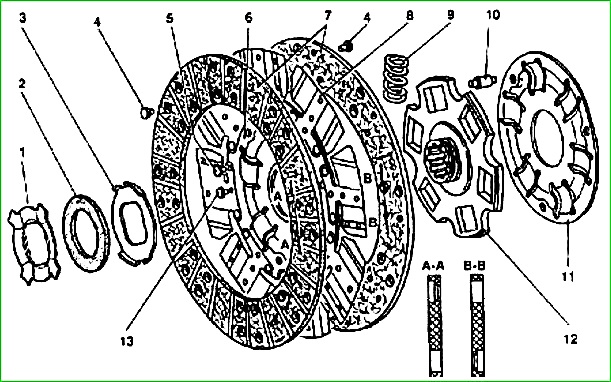
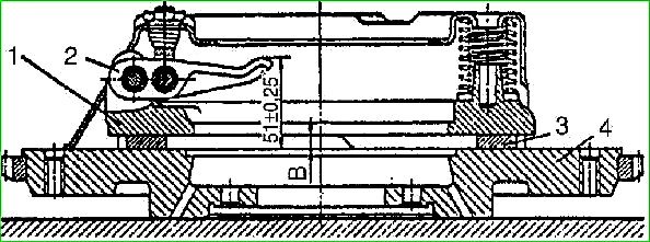
The driven clutch disc is equipped with a friction torsional vibration damper, consisting of a steel friction washer 3, sitting on the flats of the hub 12 and sandwiched between the disc 6 and the heat-insulating washer 2.
Vibration damping occurs due to friction between these parts when disk 6 with friction linings is rotated relative to the hub.
The constancy of the compression force of the washer 3, and therefore the constancy of the friction moment in the damper, is ensured by the plate pressure spring 1 fixed in the groove of the driven disk hub.
The outer diameter of the friction lining is 225 mm, the inner diameter is 150 mm, the thickness of the lining is 3.5 mm.
The size of the splines of the driven disk hub is 4 and 23 and 29 mm, the number of splines is 10.
The clutch release bearing and bearing coupling contain special lubricants that do not require replacement throughout the entire life of the vehicle.
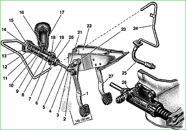
Clutch release drive
Clutch maintenance
It is necessary to check and add fluid to the working cylinder reservoir if necessary.
Check:
- - for the presence of air in the hydraulic clutch drive;
- - for possible blocking of the compensation hole of the main cylinder with the edge of the cuff;
- - for blockage of the compensation hole due to clogging.
In these cases, it is necessary to bleed the hydraulic drive, replace the cuff or wash the cylinder.
The degree of wear of the friction linings can be judged by the distance between the flywheel and the pressure plate when the clutch is engaged.
If this distance is less than 6 mm, then it is advisable to remove the driven disk to inspect and replace the friction linings.
It is recommended, if possible, to replace the driven disk assembly with linings.
Distance between flywheel and pressure plate It is advisable to check it after 60,000 km.
To take measurements, it is necessary to place the car on an inspection ditch or a lift and remove the lower stamped part of the clutch housing.
Removal, repair and installation of clutch
For repair work, the clutch can be removed from the vehicle without removing the engine. To do this, the car should be installed on an overpass, lift or inspection ditch.
To remove the clutch you must:
- - disconnect the gear shift lever from the gearbox, to do this, lift the outer rubber seal from the inside of the body to the handle of the lever, unscrew the cap located on the neck of the gear shift mechanism, and pull the lever up;
- - disconnect the release spring and cable from the intermediate lever of the parking brake drive;
- - remove the driveshaft;
- - disconnect the flexible speedometer drive cable and the reverse light switch wires from the gearbox;
- - unscrew the two bolts securing the working cylinder to the crankcase and lift up the working cylinder with the pusher without disconnecting it from the pipeline;
- - remove the clutch release fork by unscrewing the bolt securing the cover frame;
- - unscrew the fastening bolts and remove the stamped lower part of the clutch housing;
- - remove the connecting bracket for the muffler pipe suspension;
- - disconnect the cross member of the rear engine mount from the side member brackets;
- - unscrew the nuts of the studs securing the gearbox to the clutch housing and remove the gearbox along with the clutch and clutch release bearing;
- - remove the gasket between the clutch housing and the gearbox;
- - check for the presence of aligned 0 marks on the engine flywheel and pressure plate housing; if they are missing, apply them;
- - gradually unscrew the bolts securing the clutch housing to the flywheel, while turning the engine crankshaft;
- - remove the driven and clutch pressure plates from the clutch housing through the lower hatch.
To remove the hydraulic drive from the vehicle you must:
- - disconnect the pipeline from the clutch release cylinder;
- - drain the fluid from the hydraulic system through the disconnected end of the pipeline into a clean container;
- - disconnect and remove the clutch release cylinder and the slave cylinder pusher;
- - remove the clutch release pedal release spring;
- - disconnect the master cylinder pusher from the pedal, remove two plastic bushings from the pusher eye;
- - unscrew and unscrew the nut of the clutch and brake pedal axle;
- - remove the clutch pedal from the axis, remove two plastic bushings from the part boss;
- - disconnect the pipeline from the clutch master cylinder and remove the pipeline;
- - disconnect and remove the clutch master cylinder.
When disassembling the clutch housing assembly (if there is no special tool), you must:
- - make marks on the casing, levers and pressure plate to maintain balance during assembly;
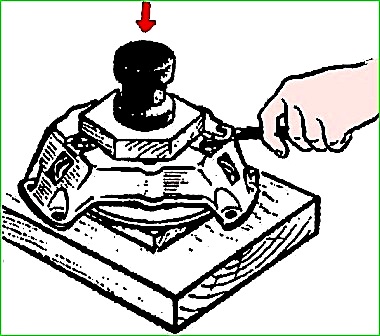
- - place the pressure disk on the press table, placing a wooden stand under the disk so that the casing feet can move down.
Put a wooden block on top of the casing so that it does not cover the three nuts securing the support forks of the clutch release levers.
Pressing on the upper bar, compress the springs and relieve the clutch release levers from the effort;
- - unscrew the nuts of the clutch release lever support forks and smoothly release the press;
- - remove the clutch cover;
- - remove the pressure springs and thermal insulating washers;
- - unscrew and remove the axes of the clutch release levers from the pressure plate ears, remove the bearing needles;
- - unscrew and remove the axles of the release levers from the support forks, remove the bearing needles.

The driven disk with new linings must be checked for runout of the friction plane.
The runout of the disk linings, measured at the edge of the disk, should be no more than 0.7 mm.
Then the disk must be subjected to static balancing using special balancing weights, which are inserted into the holes of the driven disk plate and riveted.
The number of weights should be no more than three.
The heads of the weights should be located on the side of the friction damper of torsional vibrations.
The permissible imbalance of the driven disk must be no more than 10 gsm.
Assembling the housing with the clutch pressure plate is carried out in the reverse order of disassembly.
In this case, you need to make sure that the marks made during disassembly on the casing, pressure plate and levers match, and that the pressure springs are centered on the flanges of the casing.
To prevent the needles from falling out of the holes in the levers, it is necessary to install rubber balls with a diameter of 85-8.0 mm or generously lubricate the needles with grease.
To avoid distortion of the pressure plate and to create the necessary pressing force, pressure springs must be installed only with the required load and one group.
After assembly, adjust the position of the pull levers.
If there is no special tool, this operation can be performed using the removed flywheel.
In this case, the pressure plate assembled with the clutch housing is installed on the working surface of the flywheel.
Between the pressure plate and the flywheel, washers of the same thickness - 8 mm - are placed in three places.
By tightening or unscrewing the adjusting spherical nuts of the support forks, ensure that the size from the end of the flywheel to the end of each lever is equal to (51 ± 0.25) mm
After adjustment, caulk (punch) the metal of the shank of each spherical nut into the slot of the support fork.
If the release levers, housing or pressure disk were replaced during assembly, it is necessary to statically balance the housing and pressure disk assembly by drilling metal from the pressure disk bosses that serve to install the pressure springs.
The drilling depth from the edge of the boss should be no more than 25 mm, including the drill cone. permissible imbalance of the pressure plate - no more than 25 gcm.
Assembling the hydraulic clutch release drive is done in the reverse order of disassembly.
Before assembly, the cylinder mirror must be lubricated with castor oil or fresh brake fluid.
When assembling the master cylinder, you must check that the return spring easily returns the piston to its original position.
Next, use a soft wire with a diameter of 0.3-0.5 mm to check whether the cuff is blocking the compensation hole.
The use of a master cylinder with a blocked compensation hole is prohibited.
When assembling the working cylinder, you need to make sure that the spring easily moves the piston in the cylinder.
Filling the hydraulic drive with liquid
- - fill the master cylinder reservoir with brake fluid to the normal level (15-20 mm below the top edge of the reservoir);
- - remove the protective cap from the head of the working cylinder bleeding valve and place a rubber hose on the head;
- - immerse the free end of the hose in brake fluid poured into a glass container with a capacity of at least 0.5 liters, half filled;
- - create pressure in the system by sharply pressing 4-5 times at intervals of 1-2 seconds. on the clutch pedal;
- - keeping the pedal pressed, unscrew the working cylinder bleeder valve 1/2-3/4 turn, making sure that the free end of the hose remains immersed in the liquid. Liquid with air bubbles will escape into the vessel;
- - after the flow of liquid into the vessel stops, turn the valve all the way, and then release the pedal;
- - check for fluid in the master cylinder reservoir.
Do not allow the fluid level in the tank to drop to more than 2/3 of normal during pumping and add fluid as needed;
- - repeat these operations until liquid comes out of the hose without air bubbles;
- - keeping the pedal pressed, turn the working cylinder bleeding valve all the way and then smoothly release the pedal;
- - remove the hose from the valve head and put the rubber cap on the valve head;
- - add fluid to the master cylinder reservoir to the normal level.
Do not add fluid released when bleeding the hydraulic drive to the master cylinder reservoir, as it contains air.
")

")
")
")
")
")
")
")