Adjusting the carburetor drive
Performed when replacing the carburetor, as well as when drive parts are worn out or replaced.
When the gas pedal is fully pressed, the throttle valves should be fully open, and when released, they should be closed.
If this is not the case, disconnect the end of the drive's longitudinal rod from the bracket on the valve cover (see Removing the carburetor from the engine).
Using an 8 wrench, loosen the lock nut of the tip (for clarity, we show the operation with the rod removed).
By unscrewing or turning the tip, we achieve the correct adjustment.
Tighten the locknut.

We also check the distance between the centers of the transverse rod ends, which should be 80 mm.
If the adjustment range is not enough (the dampers do not open completely), bend the gas pedal up.
Adjusting the fuel level in the float chamber
Performed when replacing a needle valve or float.
Remove the carburetor cover (see Disassembling the carburetor).

Putting the carburetor cover horizontally with the floats up, use a caliper to measure the distance from the cover gasket to the farthest point of each float.
It should be between 34–35 mm for both floats.

The gap is adjusted by bending the tongue or float arms
The supporting surface of the tongue must be perpendicular to the axis of the needle valve and must not have dents or nicks.
When installing the cover in place, check whether the floats are touching the walls of the float chamber; if necessary, bend the float arms.
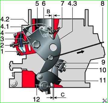
Carburetor trigger: 1 - diaphragm; 2 - adjusting screw; 3 - diaphragm rod; 4 - air damper control lever; 4.1 - lower profile of the groove of lever 4 to limit the maximum opening of the air damper; 4.2 - upper profile of the groove, providing mechanical opening of the air damper; 4.3 - edge of lever 4 to ensure starting clearance of the throttle valve of the first chamber; 5 - air damper; 6 - air damper lever; 7 - air damper return spring; 8 - air damper drive cable; 9 - adjusting screw for slightly opening the throttle valve of the first chamber; 10 - lock nut of the adjusting screw; 11 - throttle valve drive lever; 12 - throttle valve of the first chamber; B - starting gap at the air damper; C - clearance at the throttle valve
Adjusting the starter
When turning the choke control lever counterclockwise all the way, the choke should close completely.
If it does not close, eliminate the cause of the jam (or straighten the deformed valve).
With the air damper completely closed, the throttle valve of the first chamber should be slightly open to the starting gap “C”, equal to 1.1 mm.

Measure the gap with a wire of suitable diameter.

This gap is adjusted by turning the screw on the throttle drive lever with a 8" wrench (or a slotted screwdriver)
With the air damper completely closed, press the trigger rod with your finger until it stops - in this case, the air damper should open slightly to the starting gap “B”, equal to 3.0 ± 0.2 mm.

Measure the gap with a drill

To adjust the gap, use an “8” wrench to loosen the lock nut of the screw located on the starter cover.
Inserting a thin slotted screwdriver into the slot, unscrew (to increase the gap) or tighten (to decrease the gap) the screw, and then tighten the lock nut
Checking the operation of the second camera locking mechanism
Turn the air damper control lever counterclockwise until the damper is completely closed.
Then we turn the throttle control lever until the throttle valve of the first chamber is fully open.
The throttle valve of the second chamber must remain closed.
Turn the air damper control lever clockwise until it stops (the air damper should be completely open), and the throttle valve control lever until the dampers are completely open.
If the throttle valve of the second chamber remains closed, it is necessary to eliminate the jamming of the locking lever of the second chamber (the reason may also be the disconnection of the spring of the locking lever).
Adjusting the idle system
Performed during maintenance, as well as in case of engine malfunctions.
Adjustment is carried out on a warm engine.
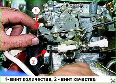
Turning the idle mixture amount adjusting screw (made of black plastic) with your fingers, set the crankshaft speed to 800±50 min –1 (for clarity, the air filter housing has been removed), and turning the screw with a slotted screwdriver quality, – the content of carbon monoxide in the exhaust gases is no more than 3%.
When you press the gas pedal, the engine should increase the crankshaft speed without interruption, and when you release the pedal, it should not stall.
When turning the quantity screw clockwise, the crankshaft speed increases.
When you turn the quality screw clockwise, the CO content in the exhaust gases decreases.
")

")
")
")
")
")
")
")