The auxiliary brake consists of a drive and two actuators installed in the connector of the exhaust pipes of the muffler
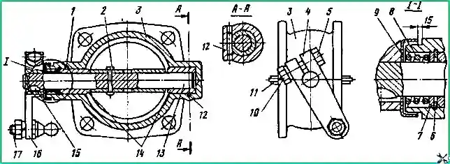
The auxiliary brake mechanism (Fig. 2) includes a housing 3, a damper 11, a shaft 13 and a lever 4.
When the brake is not engaged, the mechanism flap is located along the flow of exhaust gases and the axis of the exhaust pipes.
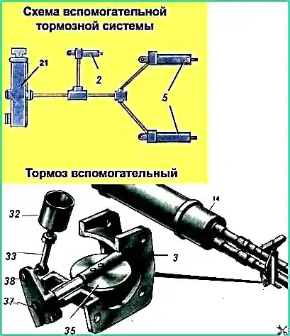
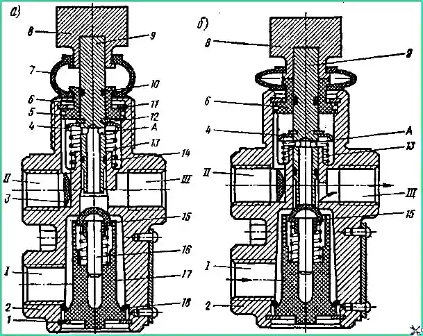
The drive for controlling the brake mechanisms is pneumatic and consists of a valve (Fig. 3), three pneumatic cylinders (pneumatic cylinders) and pipelines connecting them.
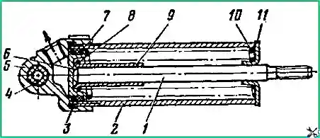
When you press the tap button, compressed air is supplied through pipelines to two pneumatic cylinders (cylinder diameter 35 mm and piston stroke 65 mm - Fig. 4), the pistons of which set the damper mechanisms perpendicular to the exhaust gas flow.
At the same time, compressed air is supplied to a 30x25 pneumatic cylinder (Fig. 5), installed on the cover of the high-pressure fuel pump, which turns off the fuel supply.
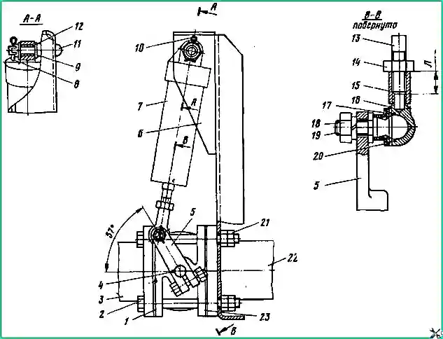
The auxiliary brake mechanisms 23 (Fig. 6) are attached with bolts 2 to the flanges in the connector of the exhaust pipes 3 and 22 of the exhaust system muffler.
Brackets 6 for installing pneumatic cylinders 7 are attached to the flanges with the same bolts.
The auxiliary brake control valve is mounted on the cab front panel, and its button is located to the left of the clutch pedal.
The auxiliary brake units are removed and partially or completely disassembled when faults are detected in them, for example, jamming of the damper shaft in the housing bushings, wear of parts of pneumatic cylinders, loosening of the bolts securing the mechanisms to the exhaust pipes, etc.
Removing and disassembling the auxiliary brake
When removing, unscrew the nut 18 of the ball pin 19 and disconnect the tip 15 from the lever 5.
Unscrew and unscrew nut 8 of pin 11, remove the washer and pneumatic cylinder 7 as an assembly. Unscrew the locknuts and nuts of the four bolts 2, remove them, remove the bracket 6, gaskets 1 and mechanism 23 assembly.
To remove the pneumatic cylinder for shutting off the fuel supply, undo the pins connecting the cylinder with the bracket and the earring on the cylinder rod with the lever of the high pressure fuel pump, and remove the cylinder assembly.
When removing the tap, unscrew the nuts and disconnect the pipelines from it.
Unscrew the nut securing the tap to the cabin floor panel and remove it. The auxiliary brake parts, being in the exhaust gas environment, are partially corroded, and the gaps between them become clogged with soot particles; therefore, to facilitate disassembly, the auxiliary brake should be soaked in kerosene or diesel fuel for 24 hours.
When disassembling the mechanism, cut off the head of rivet 2 (see Fig. 1) with a file and use a drift with a diameter of 4 mm to remove it from the shaft and valve.
Attach the auxiliary brake mechanism to lever 4 in a vice and Turning body 3, remove it from shaft 13.
Remove damper 11 from the housing.
Remove cover 9 from the body and remove spring 8, washer 7 and lock ring 6 from it. Unscrew nut 10 of coupling bolt 5 and remove lever 4 and key 15 from shaft 13.
Using a drift with a diameter of 3.5 mm, knock out pins 1 and 12 from the body and remove bushings 14.
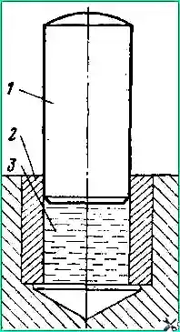
The bushing can be removed from the blind hole of the housing hydraulically (Fig. 164) using grease.
You can use the damper axis as a rod.
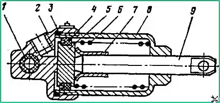
When disassembling the 35x65 pneumatic cylinder of the mechanism drive, it must be secured in a vice by the cover 5 (Fig. 161) and unscrew the housing 2, remove the sealing ring 3.
Move the piston bottom 6 out of the cylinder by 10-15 mm and secure it in the loosen lock nut 14 (see Fig. 6).
Unscrew the tip 15 and the lock nut.
Remove piston 6 (see Fig. 4) complete with rod 1 and springs 8 and 10 from the cylinder.
Remove limiter 9 from rod 1, and cuff 7 from the piston. If necessary, disassemble the tip.
Before disassembling the 30x25 fuel shut-off cylinder, you must unscrew the nut and disconnect the stop link from the rod.
Then clamp the lower part of the cylinder 8 (see Fig. 5) in a vice, unscrew the cover 2 and remove the piston 5 assembled with the rod 9 and spring 6.
Remove cuff 4 from the piston, and limiter 7 from the rod.
When disassembling the crane (see Fig. 3), secure its lower part in a vice.
Disconnect the lower part of the cover 7 from the bushing 6.
Remove the thrust ring 11 into the gap formed.
Pull button 8 and remove pusher 9 from the body, assembled with cover 7, bushing 6, sealing rings 5, 10 and 14 and spring plate 4.
Remove spring 13 from the housing.
Move the tap in the vice so that there is access to the bottom of the tap.
Remove the thrust ring 1, remove the valve guide 17 and the sealing ring 18 from the body.
Remove intake valve 15 with rod 16 and valve spring from guide 17.
Remove sealing rings 10,- 14, plate 4, thrust ring 12 and bushing 6 from pusher 9.
Parts of pneumatic cylinders, mechanisms and valves must be washed in gasoline, then dried and carefully inspected.
The gaskets between the flanges of the exhaust pipes and auxiliary brake mechanisms must not have ruptures, delaminations or other damage.
Tears, deep scratches, hardening and residual deformation, as well as other damage to rubber parts are not allowed.
Data for monitoring parts of the auxiliary brake mechanism and pneumatic cylinders are given in Table 1.
Table 1
Sleeve. Inner diameter:
- - nominal size - 14+0.050 mm;
- - permissible size - 14.10 mm
Shutter shaft. Outer diameter:
- - nominal size - 14-0.060 mm;
- - permissible size - 13.80 mm
Ball pin. Spherical surface diameter:
- - nominal size - 12-0.120 mm;
- - permissible size - 11.75 mm
Auxiliary brake drive rod end. Ball pin hole diameter:
- - nominal size - 12+0.160 mm;
- - permissible size - 12.25 mm
Assemble the auxiliary brake units and install them on the vehicle in the reverse order of disassembly and removal from the vehicle.
The following requirements must be met:
- - the damper shaft in the bushings must rotate freely without jamming. Lubrication vala and bushings are strictly prohibited;
- - lubricate tip 15 (see Fig. 6) and ball pin 19 with a thin layer of graphite grease;
- - lubricate with a thin layer of lubricant CIATIM-221: at the auxiliary brake control valve, pusher 9 (see Fig. 3) assembled with o-rings, sleeve 6 and body 2 at the point of contact with the rod; pneumatic cylinders have a piston assembled with an o-ring, a rod and a cylinder.
After assembly, check the pneumatic cylinders for leaks under air pressure of 5.3 kgf/cm².
Detect places of air leakage with soap emulsion, which should be removed after checking.
When checking, it is also necessary to measure the stroke of the rods, which for 35x65 pneumatic cylinders should be 65 mm, and for a 30x25 pneumatic cylinder - 25 mm.
The rods must return to their original position without jamming under the action of the springs.
When installing the auxiliary brake mechanism on a car, it is necessary to adjust the screwing length of the rod “L” (see Fig. 6) so that when the pneumatic cylinder piston is in the uppermost position, the key 4 is located along the axis of the receiving pipes. In this case, the mechanism damper will be completely open.
You should also check the tightness of the bolts securing the exhaust pipes of the exhaust system, and, if necessary, tighten the bolts securing the exhaust pipes to the exhaust gas pipelines of the engine.


