Regularly check the tightening of the bolts securing the final drive to the axle housing. Loosening the bolts causes the crankcase to bend
When adjusting the final drive, adjust the preload of the tapered bearings and check the contact patch in the mesh of the bevel pair of final drive gears.
Perform adjustment work with the main gear removed from the vehicle.
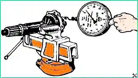
Control the amount of tension by the torque required to rotate the shaft. Determine the moment of resistance to turning using a dynamometer.

It is necessary to measure the torque on the shaft when turning it smoothly in one direction and after at least five full revolutions.
It should be borne in mind that incorrect adjustment of the bearings can lead to the destruction of not only the bearings themselves, but also the final drive gears.
Adjust the main gear in the following sequence:
Install the final drive into the fixture, remove the differential and flanges.
Unscrew the bolts securing the bearing housing of the drive bevel gear. Remove the drive gear shaft with the cup and gear.
Install the drive gear in a vice, holding it by the ring gear.
Unscrew the cover bolts and remove it.
Unlock the locknut and unscrew it.
Remove the lock and lock washers. Tighten the nut to a torque of 450–500 Nm (45–50 kgf/m).
Install the indicator device and determine the clearance in the bearings.
If there is no gap after tightening the nut, there is no need to adjust the cup bearings.
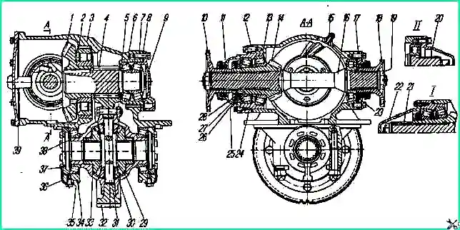
Calculate the amount of reduction in the thickness of the adjusting washer 24 (see Fig. 1) (the amount of the gap plus 0.03-0.05 mm of preload).
Unscrew the nut, remove the bearing and adjusting washer.
Grind (or size) the washer to the required size, install the washer and assemble the drive bevel gear bearing assembly. Nut tightening torque 450 - 500 Nm - (45-50 kgf/m).
Secure the locknut by bending the washer onto one of the edges.
The torque required to rotate the drive bevel gear in the bearings should be 0.6-1.4 Nm (0.06-0.14 kgf/m).
The force on the dynamometer when unwinding the cord from the surface of the glass is 7.5-17.5 N (0.75-1.75 kgf) (Fig. 2).

Adjust the preload of the intermediate shaft bearings. Adjust the bearings by selecting a package of gaskets 8 (see Fig. 1) under the cover 9 of the cup 5.
The torque required to rotate the intermediate shaft should be 0.9-1.5 Nm (0.09-0.15 kgf/m).
When measuring torque using a dynamometer, wind the cord around the rim of the spur gear, the dynamometer reading should be in the range of 18.7-31.2 N (1.87-3.12 kgf).
It should be borne in mind that when the gaskets are removed from under the cup cover, when adjusting the bearings, the driven bevel gear shifts towards decreasing the side clearance, therefore, to maintain the clearance under the cup 5 bearings, install additional gaskets.
Install the cup with the drive bevel gear into the main gear housing.
Tighten the cup mounting bolts to a torque of 60-80 N (6-8 kgf).
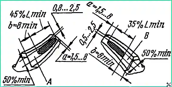
Check that the bevel gears engage the paint correctly. The length of the impression must be at least 60% of the length of the tooth (table).
The print must be located no closer than 5 mm to edges of the tooth. In this case, the lateral gap in the teeth (at the wide part) should be 0.1-0.4 mm.
To change the backlash of bevel gears without distorting the contact, move both gears a distance proportional to the number of teeth of each gear, i.e. move the driven bevel gear 2.2 times (24:11) further than the drive gear.
Install the differential and adjust the differential bearings. Tighten the differential bearing cap bolts to a torque of 250-320 Nm (25-32 kgf/m).
Adjust the differential bearings with nuts 37 (see Fig. 1). After tightening the nuts, the distance between the differential bearing caps should increase by 004-0.14 mm.
During adjustment, rotate the differential to install the rollers in the bearings. The crown of the driven spur gear must be positioned symmetrically relative to the crown of the drive gear.

To determine the contact patch, apply a thin layer of oil paint to the working surfaces of the three teeth of the drive bevel gear.
Then, by rotating the drive bevel gear shaft by the splined end in both directions, achieve a clear imprint of the contact patch on the forward and reverse sides of three to five teeth of the driven bevel gear.
The contact patch on the tooth of the driven bevel gear should be located closer to the narrow end of the tooth and not reach the edge by 1.5-8 mm (Fig. 3).
In this case, the lateral gap between the teeth (at the wide part) should be 0.1-0.4 mm. Check the gap size for at least three teeth of the driven bevel gear, located at equal distances around the circumference.
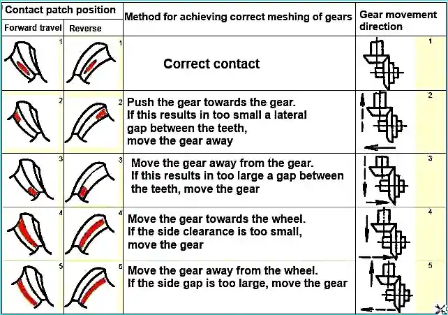
Methods for correcting the contact patch and achieving correct gear engagement are given in the table.
According to the recommendations given in the table, correct engagement is achieved by axial movement of the driven and driven bevel gears.
Move the drive bevel gear by changing the thickness of the shim pack. The set of adjusting shims produced by the plant consists of three standard sizes with a thickness of 0.22; 0.1 and 0.05 mm.
Move the driven bevel gear by changing the thickness of the pack of adjusting shims 4 installed between the flange of the bearing housing 5 and the gearbox housing.
After completing the adjustment, install the bearing caps with sealing gaskets and secure them with bolts.
Using a mandrel, press flanges onto the splined ends of the drive bevel gear shaft, tighten and cotter the flange mounting nuts.
The cotter pin installed in the hole at the rear end of the drive bevel gear shaft must be located in the direction of the straight edge of the flange (i.e., when installing the flange, it must be oriented relative to the shaft hole for the cotter pin).
The orientation of the flange on the shaft is designed to prevent contact between the cotter pin and the yoke of the installed propeller shaft.

Due to the improvement of differential gear manufacturing technology, the tooth profile of the satellite side gear has changed.
Changed gears are not interchangeable with previously produced ones and should only be replaced as a set.
For distinction, marks have been introduced on the side of the small module: on the axle gear there is a groove with a diameter of 90 mm and on the satellite there is a stepped end.
Adjust the bearings of the steering knuckle pins during the sixth maintenance -2 (after 96,000 km) in the following order:
- - remove the wheels and install stops under the lower covers of the steering knuckles;
- - remove the steering knuckle arms;
- - remove two gaskets from the package of gaskets under the levers: one 0.05 mm thick, the other 0.1 mm thick; put 50 g of Litol -24 GOST 21150-87 lubricant into the cavity of the levers and install the levers in place; tighten the nuts to a torque of 110-140 Nm (11-14 kgf/m);
- - remove the stops and remove the covers;
- - remove a package of gaskets with a thickness of 0.15 mm [(0.05+0.1) mm] from under each cover;
- - install the covers and tighten the nuts to a torque of 110-140 Nm (11-14 kgf/m);
- - install the wheels.
Adjusting wheel hub bearings:
- - jack up the axle on the side of the adjustable wheel;
- - remove the cover;
- - use a puller to remove the axle shaft splines from engagement with the hub and remove the axle shaft;
- - unscrew the outer nut and remove the locking and locking nut personal washers;
- - by rotating the wheel by hand, make sure that there is no friction between the brake drum and the pads;
- - tighten the nut to a torque of 200-250 Nm (20-25 kgf/m), when tightening the nut, turn the hub to self-install the rollers in the bearings, then loosen the nut by about 1/5-1/6 of a turn. Install the lock washer
If the nut pin does not coincide with the slots of the lock washer, it is allowed to loosen the nut by an amount not exceeding the distance between two adjacent slots.
Install the lock washer, tighten the lock nut to a torque of 400-500 Nm (40-50 kgf/m) and lock it.
To ensure the connection of the wheel inflation hose to the wheel crane, install the axle shaft with the hub cover so that the inflation hose is located in the direction of the wheel crane symmetrically between the wheel mounting studs.
After completing assembly, check the adjustment of the wheel bearings during a run of 10-20 km.
When adjusted correctly, the hub should be cold or slightly warm. If the hub heats up noticeably to the touch, check the bearing adjustment.
On commercial vehicles, wheel hub bearings 2007124A can be installed, which are not interchangeable with bearings 2007124M.
The wheel hub with the outer rings of bearings 2007124A pressed into it is marked with an annular groove on a diameter of 220 mm, a width of 2-4 mm at a distance of 38 mm from the end under the hub cover.
Assembling a hub with outer rings of bearings 2007124A and inner rings of bearings 2007124M pressed into it (and vice versa) is unacceptable.
The cuff race for bearing 2007124M cannot be used with bearing 2007124A.
The cuff race for bearing 2007124A can be used with bearing 2007124M.
The cuff race used with bearing 2007124A has an enlarged groove for the cage (diameter 175 mm instead of 172 mm).
Assembling cuff races with bearings that do not correspond to them is unacceptable. Wheel hubs and bearings are interchangeable.


