One of the characteristic signs indicating the need to disassemble and adjust the gearbox is increased noise when the vehicle is moving. Causes of increased noise:
- - displacement of the contact patch in the meshing of bevel gears as a result of improper adjustment of the tapered bearings;
- - scuffing and chipping of gear teeth, wear of bearings, as well as insufficient oil level in the axle housing.
Dismantling of drive axles and their gearboxes
The procedure for dismantling the middle (rear) drive axle is as follows.
Place the car on the inspection ditch. Close the wheel taps (only for Ural-4320 and 4420).
Loosen the tightening of the wheel nuts of the bridge being dismantled, remove the protective covers and disconnect the air supply hoses from the wheel valves.
Drain the lubricant from the axle housing.
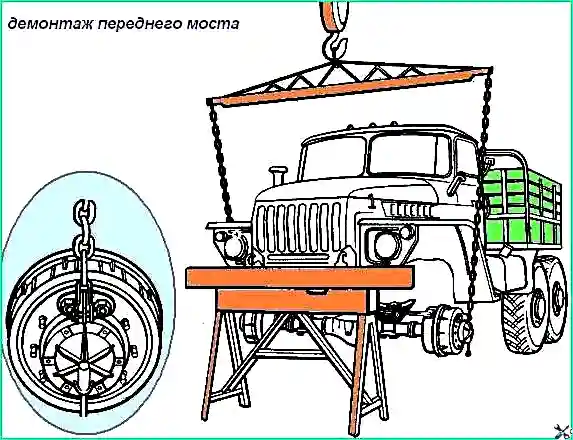
Raise the rear of the car and install a stand under the rear end of the frame.
Unscrew the wheel nuts and remove the wheels. Install and secure the device (Fig. 1).
Using adjusting eccentrics, spread the brake pads, thereby preventing the axle beam from turning during subsequent disassembly operations.
Remove the drive shaft of the middle (rear) axle, disconnect the brake hoses and pipelines, sealing systems (only for Ural-4320 and 4420), and tire inflation systems.
Disconnect the upper reaction rod bracket from the bridge beam, disconnect and remove the lower reaction rods.
Roll the installation trolley under the bridge and, having removed the bridge beam assembly, lower it onto the trolley using the device.
Disconnect the device and roll out the trolley with the driving middle (rear) axle from under the car.
When removing the front axle, carry out preparatory work similar to those described above. Additionally, it is necessary to disconnect the bipod rod of the steering mechanism from the left steering knuckle lever, the hydraulic booster from the right steering knuckle lever.
Disconnect and remove the lower shock absorber heads from the brackets.
Using the installed and secured device, lift the bridge and, unscrewing the nuts of the stepladders, remove the clamps securing the front springs.
Lower the front drive axle onto the trolley.
Removing gearboxes from a vehicle
The front axle gearbox, unlike the middle (rear) axle gearbox, must be dismantled only after removing the axle assembly from the vehicle.
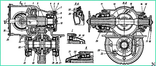
Main gear: 1 - gear housing; 2 - gear housing ring; 3 - driven bevel gear assembly; 4, 6, 11 - shims; 5 - cup of bearings of the drive cylindrical gear; 7, 14, 34. 34 - sealing gaskets; 8 - tapered roller bearing; 9 - bearing cup cover; 10 - pressure washer; 12 - drive bevel gear shaft assembly; 13 - plug with sealing tube assembly; 15 - rear bearing cover; 16 - flange; 17 - flange mounting nut; 18 - cylindrical roller bearing; 19 - rear bearing cover of the rear axle; 20 - shaft spacer; 21 - bearing cover of the drive bevel gear; 22 - differential bearing cover mounting bolt; 23, 27 - locking plates; 25 - oil supply fitting; 26 - sealing ring; 28 - bolt securing the locking plate; 29 - differential bearing cover; 30 - differential assembly: 31 - lock washer; 32 - differential bearing adjusting nut; 33 - tapered roller bearing of the differential; 35 - gearbox housing cover with oil catcher assembly; I - for the rear axle; II - for the front axle
Place the dismantled front axle on stands. Disconnect the steering linkage, brake hoses and sealing systems.
Unscrew the nuts securing the ball joints.
Using a spatula, remove the steering knuckle assemblies using the grooves of the ball joint flanges.
Remove the side cover 35 (see Fig. 2) of the gearbox housing assembly with the oil supply fitting 25 and unscrew the bolts and nuts securing the gearbox housing, including two bolts located inside the housing.
Using a lifting mechanism, remove the gearbox from the axle housing.
Using a device, remove the middle (rear) axle gearbox directly from the vehicle installed on the inspection ditch; to do this, close the wheel taps, remove the protective covers and disconnect There are air supply hoses from wheel cranes.
Drain the lubricant from the axle housing.
Unscrew the bolts securing the hub covers, unscrew the air supply elbows from the axle shafts and remove the hub covers together with the seals and air supply hoses.
Then remove the axle shafts using a puller.
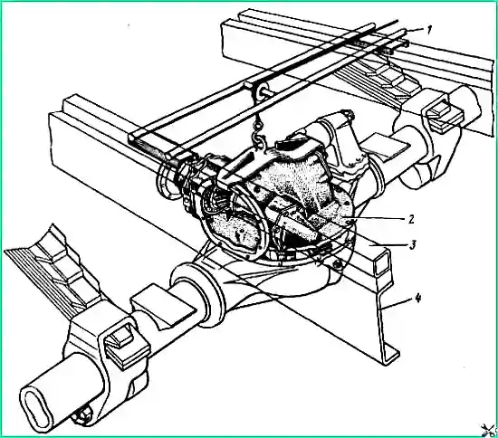
Remove the drive shaft of the middle (rear) axle. Disconnect and move aside the upper reaction rod bracket together with the rod, pipelines and hoses of the brake system and sealing system
Remove the side cover of the gearbox assembled with the oil supply fitting, unscrew the bolts and nuts securing the gearbox housing, including two bolts located inside the housing.
Install the device and remove the gearbox from the axle housing (Fig. 3).
Disassembling the gearbox
The article describes disassembling the middle axle gearbox. Dismantling the front and rear axle gearbox is carried out in the same way.
Bend the locking plates 23 (see Fig. 2) and lock washers 31, unscrew the bolts 28 and 22.
Remove differential bearing caps 29.
It should be borne in mind that the holes in the gearbox housing for the differential bearings are processed together with the covers, and before disassembling the cover and the crankcase support on which they are installed, mark them with a core or paint, thereby preventing the covers from becoming depersonalized.
Remove the adjusting nuts 32 and the outer rings of the bearings 33.
Remove differential 30 assembly.
Unscrew and unscrew the nut securing flange 16 of the drive bevel gear shaft, stopping the shaft from rotating.
Use a puller to remove the flange.
Unscrew the cover bolts 15 and remove the cover assembly with the sealing collar.
Unscrew the bolts securing the bearing housing and remove the shaft assembly with the bearing housing, drive bevel gear, shim pack 11 and inner ring of the rear bearing 18 from the gearbox housing.
Remove the package of adjusting shims 11 from the bearing housing. Unscrew the bridge sealing plug 13.
Unscrew the bolts securing the cover 9 of the drive cylindrical gear bearing housing and remove the cover together with the shim pack 6.
Unscrew and unscrew the bolts securing the pressure washer 10, remove the washer.
Using a puller or two bolts for securing the cover 9, press out the cup 5 along with the tapered bearings 8 and the pack of shims 4, using the special threaded holes in the cup flange for this purpose.
Secure the packs of adjusting shims to the cover 9 and the bearing housing 5. Through the side window, remove the driven bevel gear assembly from the gearbox housing.
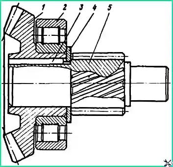
If necessary, press the outer ring of the bearing 2 (Fig. 4), the outer ring of the bearing 18 (see Fig. 2) assembled with the rollers from the seats of the gear housing and remove the oil supply fitting 25 from the hole in the side cover of the gearbox.
Disassembling the driven bevel gear assembly
Install the bevel gear on the stands and press out the drive spur gear shaft. Remove the support washer from it and remove the key from the shaft groove.
Install the driven bevel gear assembly with the inner ring of the bearing on the supports and, using a mandrel and three rods installed in the holes of the gear, remove the inner ring and bearing assembly with the rollers.
If necessary, use a mandrel to press the tapered bearings out of the glass.
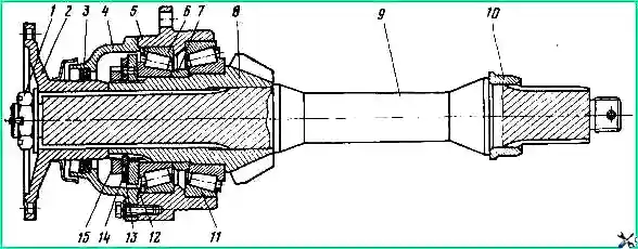
Disassembling the drive bevel gear shaft assembly. Secure the drive gear shaft assembly in a vice.
Unscrew and unscrew nut 1 securing flange 2 (Fig. 5), remove the flange using a puller.
Unscrew the bolts securing the cover of the 4 front bearings, remove the cover assembly with the sealing lip.
Bend washer 14 and unscrew locknut 15. Remove bend washer 14 and lock washer 13 and unscrew nut 12.
Install the drive gear shaft assembly on stands and press out the shaft.
Install the bearing housing assembly with the drive gear on the supports and lightly tap the end with a copper hammer to press the bevel gear out of the housing along with the inner ring of the bearing 11 and the adjusting washer 7.
Remove the inner ring of bearing 6 assembled with rollers from the glass. Remove the adjusting washer from the drive bevel gear shaft.
Using a puller, remove the inner ring of bearing 11 assembled with the rollers.
If there are burrs or significant wear on the outer rings of bearings 6 and 11, press the rings out of the cup.
If necessary, use a mandrel to press the sealing collars out of the bearing caps of the drive bevel gear shaft and remove the inner ring 10 of the bearing from the rear journal of the shaft.
Disassembling the differential
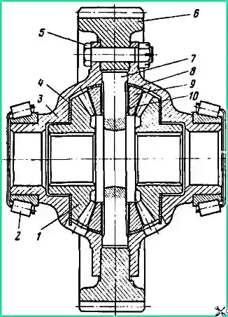
Install the differential in a vice, clamping the rim of the driven spur gear 6 (Fig. 6).
If it is necessary to replace bearings 2, remove them using a puller.
Mark the relative positions of cups 3 of the differential with a core or paint (the holes for the differential crosspiece are machined as an assembly, and during disassembly it is necessary to maintain the relative position of the cups).
Unscrew and unscrew the nuts of bolts 5 securing the differential cups, remove the bolts.
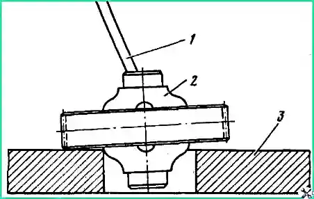
Install the differential on the fixture plate (Fig. 7).
Insert a mounting blade into the spline hole of the differential side gear and use it to lift the end of the driven spur gear above the plate.
Use sharp blows of a hammer on the end of the gear ring to press out the differential cup.
Remove gear 1 of the axle shaft (see Fig. 6) with support washer 4.
Remove crosspiece 7 assembled with satellites 9 (10 - satellite bushing) and supporting spherical washers 8.
Remove the axle gear with the support washer from the second differential cup.
Press out the second differential cup.
Technical condition monitoring
Check the condition of the body parts of the bridges by external inspection.
Operation of a vehicle with the following defects is not allowed:
- - cracks on the axle housing and axle housings; deflection of the bridge beam is more than 4 mm;
- - wear and tearing of the threads in the holes for the drain and fill plugs, in the holes for the bolts and studs for fastening the gearbox.
To check the deflection (Fig. 8), install the bridge beam on the prisms with the necks of the axle housings under the outer bearings of the hubs.

Ensure that the plane of the axle housing connector is parallel to the plane of the control plate. Determine the dimensions “B” and “C” with an accuracy of 0.5 mm and calculate the deflection “H” of the bridge beam using the formula:
Н = (B - 60) - (C - 71.25), where “B” is the actual size from the plane of the control plate to the upper part of the axle shaft journal; C - actual size from the plane of the control plate to the plane of the bridge housing connector in the middle part.
The bridge beam, which has a deflection of more than 4 mm, should be straightened. The diagram for straightening the bridge beam is shown in Fig. 9.

When inspecting the gearbox parts, it should be borne in mind that the main gear and differential gears are not allowed to have cracks or chips in the middle part of the tooth, or pitting on an area of more than 25% of the tooth surface.
Gears that have chipped tooth tips at a length of no more than 5 mm from the tooth end are allowed for further work after cleaning the chips.
When discarding the drive cylindrical gear or one of the gears of the bevel pair of the main gear, it should be borne in mind that, according to the manufacturing technology, these three gears are included in the kit and must be replaced as a complete set.
It is permissible to replace the drive cylindrical gear or bevel pair with the obligatory check of the size of the driven bevel gear neck under bearing 2 (see Fig. 10) after it is pressed onto the shaft of the drive cylindrical gear.
The diameter of the bearing journal after pressing on the driven bevel gear should be in the range of 90.012-90.035 mm.
Runout relative to the axis of the drive spur gear - no more than 0.05 mm.
The kit also includes differential cups. If it is necessary to replace one of the cups, they should also be replaced as a whole.
Bearings that have chips, cracks, destruction of cages, as well as chipping, cavities, deep scratches and brinelling on the ring raceways and rollers should be discarded.
Replace the sealing cuffs of the axle shafts of the front drive axle and gearbox bearing caps if the working edges are torn, worn, hardened or cracked.
It is not allowed to loosen the fit of the cuffs in the races and bearing caps.
When replacing the sealing cuff of the front axle axle shaft, after pressing it into the hole of the axle shaft housing, lock the cuff body by punching at two points.
On the parts of constant velocity joints (forks, knuckles and discs), worn-in (smoothed) scuffs are allowed, which are the result of the mutual running-in of new parts during the break-in period.
Step wear on discs and knuckles is not allowed.
Assembling and adjusting the gearbox
Before general assembly of the gearbox, assemble the components, lubricate with sealing lubricant, the threaded surface of the sealing plug, the mating surfaces of the covers and the gearbox housing.
Before installation, lubricate the bearings with transmission oil, and the working edges of the sealing collars with CIATIM-201 lubricant.
Assembling and installing the driven bevel gear assembly
Using a mandrel, press the inner race of bearing 2 assembled with rollers onto the neck of the driven bevel gear 1.
Press key 3 into the groove of the shaft of the drive cylindrical gear 5, install the support washer 4 on the shaft and press the driven bevel gear assembly with the inner ring of the bearing 2.
In case of discarding and replacing one of the gears, assemble the driven bevel gear assembly in the following order.
Press driven bevel gear 1 onto gear shaft 5, check the size and runout of the journal for bearing 2.
The diameter of the journal after pressing should be in the range of 90.012 - 90.035 mm, and the runout relative to the axis of the drive spur gear should not be more than 0.05 mm. If necessary, grind the neck.
After processing the journal, press out gear 5 and assemble the driven bevel gear assembly in the manner described above.
Install the gear housing and secure it in the fixture.
Press the outer ring of bearing 2 into the gearbox housing if it was pressed out during disassembly.
Using a mandrel, press tapered bearings 8 (see Fig. 2) into cup 5 and install the cup with a package of adjusting shims 1 into the hole in the gearbox housing. Install and secure with two bolts the 9th bearing cup cover.
Install the assembled driven bevel gear assembly through the side window of the gearbox housing.
Unscrew the two bolts securing the cover 9 and remove the cover. Install and secure the pressure washer 10. Seal the bolts securing the pressure washer with wire.
Install and secure the bearing cup cover 9 with sealing gasket 7 and shim pack 6.
Check and, if necessary, adjust the preload of bearings 8 by selecting the thickness of the shim pack 6.
The amount of torque required for smooth rotation of the driven bevel gear assembly must be in the range of 0.09 - 0.15 kgf/m, which corresponds to a force of 1.75 - 2.93 kgf applied to the drive spur gear.
When checking the bearing preload adjustment, local seizure of up to 0.4 kgf.m is allowed.
Measure the amount of torque during continuous smooth rotation of the driven bevel gear assembly no earlier than after five full revolutions.
Assembling and installing the drive bevel gear shaft assembly
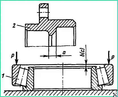
Before assembling the unit, determine the required thickness of the adjusting washer 7 (see Fig. 5).
To do this, determine the thickness of the cup collar 5 (dimension a - Fig. 10) and the distance between the ends of the inner and outer rings of the cup bearings (dimensions b and c) with an accuracy of ± 0.05 mm.
Required thickness of the adjusting shim would be determined by the formula
S= (a + b + c) - 0.05, where a is the thickness of the cup collar; b - actual size from the end of the inner ring of the front bearing of the cup to the end of the outer ring; c - actual size from the end of the inner ring of the rear bearing of the cup to the end of the outer ring.
Having determined the size S, select an adjusting washer of the appropriate thickness.
At the factory, the preload of the tapered bearings of the unit is adjusted by selecting an adjusting washer of the required thickness.
The set of factory-produced adjusting washers consists of 29 pieces. thickness 14.00; 14.05; 14.10; 15.40 mm.
If a set of shims is not available and it is necessary to reduce the thickness of the existing shim, grinding it is allowed.
Using mandrels, press the outer rings of bearings 6 and 11 into cup 5 (see Fig. 5) until they touch the cup collar. Press the inner ring of bearing 11, complete with rollers, onto the journal of drive bevel gear 8.
Press gear 8 onto shaft 9 and secure the assembled unit in a vice, as shown in Fig. 11.
Install adjusting washer 7 on the neck of the drive bevel gear (see Fig. 5); in this case, the wider end of the washer should be facing towards the gear ring gear.
Install the bearing cup 5 and, using a mandrel, press the inner ring of the bearing 6 assembled with the rollers onto the gear shaft journal until it stops against the adjusting washer.
Screw nut 12 onto the gear shaft and tighten it.
The tightening torque of the nut should be within 45-50 kgf/m.
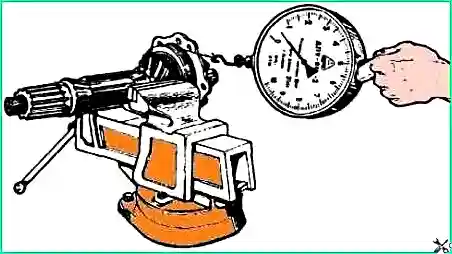
Tap several times with a copper drift and turn the bearing cup so that their rollers take the correct position.
Measure the amount of torque required for smooth rotation of the drive bevel gear bearing housing.
The amount of torque should be in the range of 0.06-0.14 kgf/m, which corresponds to a force of 0.75-1.75 kgf applied to the bearing frame.
Measure the amount of torque during continuous smooth rotation of the bearing cup no earlier than after five full revolutions.
If, when measuring the torque value, the rotation force of the cup is less than 0.75 kgf or more than 1.75 kgf, select an adjusting washer whose thickness is respectively 0.05 mm less or more.
Having finished adjusting the bearings, install lock washers 13 and bend washers 14.
If, when installing the lock washer, the pin of nut 12 does not fit into the hole of the lock washer, tighten the nut (loosening the nut is not allowed).
If it is not possible to tighten the nut, you can cut the hole in the washer until it matches the nut pin. Tighten locknut 15 and lock it with bend washer 14. The tightening torque of the locknut should be 45 - 50 kgf/m.
Install the inner race of bearing 10 onto the journal of the rear end of the drive bevel gear shaft.
Install the assembled and adjusted unit with a package of adjusting shims 11 (see Fig. 2) into the gearbox housing. Secure the drive bevel gear housing with bolts.
Using a mandrel, press the outer race of the bearing 18 assembly until the rollers stop against the shoulder of the inner ring of the bearing.
For further adjustment of the contact patch of the gears, see the article “Adjusting the axle gearbox of a Ural vehicle.”
After completing the adjustment, install the bearing caps with sealing gaskets and secure them with bolts.
Using a mandrel, press flanges onto the splined ends of the drive bevel gear shaft, tighten and cotter the flange mounting nuts.
The cotter pin installed in the hole at the rear end of the drive bevel gear shaft must be located in the direction of the straight edge of the flange (i.e., when installing the flange, it must be oriented relative to the shaft hole for the cotter pin).
The orientation of the flange on the shaft is designed to prevent contact between the cotter pin and the yoke of the installed propeller shaft.
Assembling and installing the differential
Before assembly, lubricate the mating surfaces of the semi-axial gears, satellites and differential crosspieces with transmission oil.
If, when disassembling the differential, the inner rings of bearings 2 were removed (see Fig. 6), install both cups 3 of the differential on the plate and, using a mandrel, press the bearing rings assembled with the rollers until they stop at the ends of the cups.
Install one of the differential cups onto the stand. Install driven cylindrical gear 6 on the differential cup, aligning the holes in the cup and gear for mounting bolts 5.
Install support washer 4 and axle shaft gear 1 into the differential cup. Install four sa on the spikes of the cross 7 tellite 9 with supporting spherical washers 8. Place the crosspiece assembled with satellites in the sockets of the differential cup.
Place the second axle gear with the support washer on the satellites.
Place the support washer on the journal of the semi-axial gear so that after installing the second differential cup, the washer's whiskers fall into the lubrication holes of the cup.
Install the second differential cup, aligning the marks made during disassembly.
Insert bolts 5 into the holes of the differential cups and the hub of the driven spur gear, screw the nuts onto the bolts. Install the bolts on the side of the larger recess of the gear hub.
Install the differential in a vice, clamping the rim of the driven spur gear. Tighten the nuts of the differential cup bolts.
Check that the differential is assembled correctly. The rotation of the gears in the assembled differential must be free when turning the axle gear using a splined mandrel.
After completing the check, tighten the nuts of the differential cup bolts.
Install the assembled differential onto the gearbox housing supports; in this case, the crown of the driven spur gear should take a position symmetrical relative to the crown of the driving spur gear, and the heads of the bolts securing the differential cups should be directed towards the driven bevel gear.
Install the outer bearing races and place the differential bearing caps in accordance with the marks made during disassembly. Tighten the cover bolts. Bolt tightening torque 25 kgf/m.
Tighten the adjusting nuts until the ends of the nuts and the outer rings of the bearings touch.
Adjust the differential bearings. To do this, install an indicator bracket and, by tightening one of the adjusting nuts, increase the distance between the differential bearing caps by 0.15 - 0.25 mm. At the same time, to ensure correct installation of the bearing rollers, rotate the differential several times by the driven spur gear.
After completing the adjustment, install locking plates 27 into the grooves of the adjusting nuts (see Fig. 2) and secure them with bolts 28.
Secure the corresponding bolts by bending the locking plates 23 and locking washers 31. Screw the axle sealing plug into the hole in the gearbox housing.
Check the operation of the assembled gearbox by rotating it by hand using the flange of the drive gear shaft. In this case, the gears should rotate without noticeable jamming.
Gearbox test
Run in the assembled drive axle gearbox on a special stand, and if a stand is not available, carry out a test run on the vehicle.
The gearbox is tested on a stand with reversing and braking at a rotation speed of the drive bevel gear shaft of 1000 rpm.
To avoid scuffing and seizing, the duration of the test should not exceed 0.5 minutes.
Evidence of proper assembly and adjustment of the gearbox is the absence of knocks, increased gear noise and the presence of a contact patch on both sides of the driven bevel gear tooth.
If there is increased noise or knocking, disassemble the gearbox. Check the adjustment of the bearings, the position of the contact patch and, if necessary, repeat the gearbox adjustment.
Testing drive axles. After assembly, run the drive axle on a stand without load.
Run in at a rotation speed of 1200 - 1500 forward and reverse for one minute. And at a rotation speed of 2400 - 2600 in forward gear for 3 minutes.
Before testing, pour 4 liters of I-20A industrial oil into the axle housing. During break-in, check the smoothness and noise of the gearbox, as well as the operation of the front axle hinges by turning the hubs in both directions.
After running in, drain the oil from the axle housing.
Check the drive axles of the Ural-4320, -4420 vehicles for tightness of the air supply cuffs, as well as the gearbox connections, axle beams and steering knuckle assemblies.
Check the air supply cuff for leaks for 10 minutes under an air pressure of 3.2 kgf/cm².
Plug the threaded holes in the axle housings (or the front axle steering axle fittings) for the flexible hoses of the tire inflation system.
Supply air through air supply hoses.
Air leakage during testing is not allowed.
Check the tightness of the connections of the middle (rear) drive axle by supplying air through the hole in the gearbox housing under the plug of the sealing system.
When testing the front drive axle, check the tightness of the connections of the gearbox and steering knuckle assemblies, while simultaneously supplying air through the holes in the steering knuckle housings and the gearbox housing under the fittings and plug of the sealing system.
Air pressure during testing is 0.35 kgf/cm², permissible drop in air pressure is not more than 0.1 kgf/cm² for 1 minute.
During the testing process, make several revolutions of the drive bevel gear shaft, as well as pull both steering knuckle housings of the front axle from one extreme position to the other.
Install the gearbox (axle) on the vehicle in the reverse order of dismantling. After tightening the bolts and nuts securing the gearbox housing, secure the two bolts located inside the housing with wire.
When installing the side cover of the gearbox housing, cover both sides of the sealing gasket 34 (see Fig. 2) with a thin layer of oil paint.
Having secured the side cover of the front axle gearbox, lock the two screws securing the cover by punching at two points.


